 Facebook
 Google
 GitHub
 Linkedin
Hi.
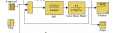
i am given a controller T*s/(k*s+k) and a motor k/(T*s^2+s). the controller controls the ac motor. i am required to modify the Simulink block diagram by breaking the controller transfer function into its components and then sending the output to the motor in order to control the motor. i am also given the expected output, bode diagram and signal characteristics of the system. now when i start modifying the controller transfer function, during the process I come to a stage that I need to use the derivative block as shown in the following link (https://www.mathworks.com/help/simulink/slref/derivative.html#br3m9zv-1 ). when i add the derivative block to the system now i am sure that my broken transfer funciton is equal to the given controller transfer function. but there is one problem as i am given the expected output of the system so finally my modified design should also have the same output becouse i didnt bring anything new i just broke the transfer function into its components and then connected all the blocks together so at the end i get the same transfer function BUT my modified version output has a litlle bit noise and the settling time increase. according the MATLAB website i found that the noise is becouse of the derivative block and they have a given a solution (that the derivative block should be replaced by a filter [s/cs + 1] where c=1/fc as shown in the following link https://www.mathworks.com/help/simulink/slref/derivative.html#br3m9zv-1 Now since i am given all of the expected signal characteristics, bode diagram and output signal as shown in the following link ( https://drive.google.com/open?id=0B9NQhKDld_D4T0xwZTdZY1V6NHM ) so can someone help me that how should i choose the value of fc for the filter so that i can get the expected output?
i am given a controller T*s/(k*s+k) and a motor k/(T*s^2+s). the controller controls the ac motor. i am required to modify the Simulink block diagram by breaking the controller transfer function into its components and then sending the output to the motor in order to control the motor. i am also given the expected output, bode diagram and signal characteristics of the system. now when i start modifying the controller transfer function, during the process I come to a stage that I need to use the derivative block as shown in the following link (https://www.mathworks.com/help/simulink/slref/derivative.html#br3m9zv-1 ). when i add the derivative block to the system now i am sure that my broken transfer funciton is equal to the given controller transfer function. but there is one problem as i am given the expected output of the system so finally my modified design should also have the same output becouse i didnt bring anything new i just broke the transfer function into its components and then connected all the blocks together so at the end i get the same transfer function BUT my modified version output has a litlle bit noise and the settling time increase. according the MATLAB website i found that the noise is becouse of the derivative block and they have a given a solution (that the derivative block should be replaced by a filter [s/cs + 1] where c=1/fc as shown in the following link https://www.mathworks.com/help/simulink/slref/derivative.html#br3m9zv-1 Now since i am given all of the expected signal characteristics, bode diagram and output signal as shown in the following link ( https://drive.google.com/open?id=0B9NQhKDld_D4T0xwZTdZY1V6NHM ) so can someone help me that how should i choose the value of fc for the filter so that i can get the expected output?
Last edited:


")


