Facebook
 Google
 GitHub
 Linkedin
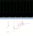
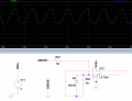
I am trying to simulate a zero crossing detection circuit from analog systems LTSpice. I am sensing the resonant current in my resonant half bridge design with a sense resistor, and attempting to generate a PWM switching waveform when the current crosses the zero mark.
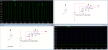
It looks as though the circuit is indeed detecting the zero crossing point, but the result is not what I expect - please see attached which shows the translated sensor voltage (blue) and the resultant output from the fast comparator (green).
My switching frequency is 300kHz, but may be increased eventually. I am unsure whether the issue is that the analog circuit is unable to detect the zero crossing points at this frequency.
If there are any suggestions for this circuit or even alternative, better performing circuits then please do let me know.
Attachments
-
 27.6 KB Views: 43