 Facebook
 Google
 GitHub
 Linkedin
Hi Guys,
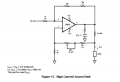
I am working on a project where I have to drive a Peltier device using an Arduino. After filtering and shifting the voltage level of a PWM signal, I am feeding this to a high current source/sink circuit. This circuit uses a TI LM675t op-amp and I got this circuit from its datasheet. A circuit like this was used in a similar project and it worked. I have a problem in understanding how this particular circuit works or how they got the equations in the datasheet. I would really appreciate it if someone could help me understand this.
Thanks!
Attachments
-
 25.8 KB Views: 25


