help with voltage circuit

Thread Starter

david1234

Joined Nov 27, 2013
104
Hello
i want to built a circuit that will give me "1" when the voltage is higher then 10.5V and "0" when lower
this circuit need to be connected to a battery and a digital I\O - so when it does under 10.5V I will know I need to cahnge the battery soon.
so I only need it to be as small as possible and will use very low current
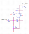
I was thinking of using LM741 (will work on 12-10V ?)and connect to him a D flipflop maybe ?
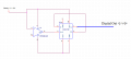
this is a sketch of what I have in mind
but how do I make it compare from 10.5V -
all use the same battery
Thanks ,
 

Attachments

alfacliff

Joined Dec 13, 2013
2,458
why not a zener diode to determine the voltage? a 10.5 vot zener with a resistor in the ground line. if theres voltage drop across the resistor, thevoltage is above 10.5 volts.
 

ErnieM

Joined Apr 24, 2011
8,377
If I read you correctly you just want a light to come ON when it is time to change the battery? That is very do-able. (If instead you are either turning things off or turning on a charger things get more complicated as the voltage you are reading change in both cases.)

Basically you need three things: a (single) comparator (with specs to work on a single supply in that 10-11 volt range), a voltage reference of well below the 10V, and some resistors to make a voltage divider.

The reference is to give you a fixed voltage for comparison no matter what the battery is doing, that is why it is a lower voltage then 10V. The resistive divider is to get a voltage equal to the reference when the battery drops to the 10 volts.

The comparator compares these two voltages, and then drives the LED. I could sketch this up at another time (no schematic stuff on this machine).
 

alfacliff

Joined Dec 13, 2013
2,458
comparators are not needed, if you want one, use it. there is a similar circuit used on ower supplies called an overvoltage crowbar consists mainly of a zenerdiode, scr and a few resistors. when the voltage rises to the zeners conduction point, it triggers the scr, shorting the output. similarly, a zener in series with a resistor will conduct if the voltage stays above the zener voltage, giving you a drop across the resistor you can use for your alarm.
 
comparators are not needed, if you want one, use it. there is a similar circuit used on ower supplies called an overvoltage crowbar consists mainly of a zenerdiode, scr and a few resistors. when the voltage rises to the zeners conduction point, it triggers the scr, shorting the output. similarly, a zener in series with a resistor will conduct if the voltage stays above the zener voltage, giving you a drop across the resistor you can use for your alarm.
An LM393 dual comparator is the textbook solution for this problem.

Why go against the grain?
 

Johann

Joined Nov 27, 2006
190
Hello,

The LM358 is a dual opamp.

The LM339 is a quad comparator:
http://www.ti.com/lit/ds/symlink/lm339-n.pdf

The LM393 is a dual comparator:
http://www.ti.com/lit/ds/symlink/lm393-n.pdf

Bertus
True, however, LM358 configured as a comparitor works well; I've used it in many temperature controllers with great success.
The LM 393 is the correct choice, theoretically. It is an open-collector output device and when used, should always have the pull-up resistor on its output. This resistor is not needed when you use the LM358 (as comparitor).
 

Thread Starter

david1234

Joined Nov 27, 2013
104
I understand I need to use LM393 with this circuit ,but
where do I make the calculation about the voltage I want it to go "high"?
what resistors I need to change in order to compare above and lower then 10.5v?

and the battery is always connected to it so all the power for the circuit and the compering will do from the same power source -not a problem right?
 

Attachments

True, however, LM358 configured as a comparitor works well; I've used it in many temperature controllers with great success.
The LM 393 is the correct choice, theoretically. It is an open-collector output device and when used, should always have the pull-up resistor on its output. This resistor is not needed when you use the LM358 (as comparitor).
Not really. The LM358 output cannot source to the supply rail or sink to absolute ground.
You can get away with it in some applications though I guess.
 
I understand I need to use LM393 with this circuit ,but
where do I make the calculation about the voltage I want it to go "high"?
what resistors I need to change in order to compare above and lower then 10.5v?

and the battery is always connected to it so all the power for the circuit and the compering will do from the same power source -not a problem right?
OHMs law is your friend. It is all OHMs law that you need to learn.
 

Dodgydave

Joined Jun 22, 2012
11,304
Your obviously not listening, you need to make a comparator , not a schmitt trigger, replace the 741 op amp for your op amp , and adjust the Vr2 so the led comes on at 10.5v, the led will go out at higher voltage.
 

Thread Starter

david1234

Joined Nov 27, 2013
104
I'm listening
so you are saying this is a much better\nicer\clean solution ,right?

I will build this , but why not use the 741?
what do I need to use?

Thanks,
 

Thread Starter

david1234

Joined Nov 27, 2013
104
I need to connect it to a digital Input of a device
and this is his spec
Connection type TTL
Voltage
To Trigger (high) Logic Level 0: 0 ~ 0.4 V
Normal (low) Logic Level 1: 3.3 ~ 30 V
Current 10mA~100mA
 
I need to connect it to a digital Input of a device
and this is his spec
Connection type TTL
Voltage
To Trigger (high) Logic Level 0: 0 ~ 0.4 V
Normal (low) Logic Level 1: 3.3 ~ 30 V
Current 10mA~100mA
High and low are reversed it seems.

Normal TTL (Transistor Transistor Logic) -- chips are as follows:

High > 2VDC
Low < 0.8VDC

Current drain would be in the range of (I've actually forgotten :D)
I did study this back in 1997. Long time ago!
 
Top