Help with turn signal circuit

Thread Starter

Moose764

Joined Dec 29, 2018
23
Hi all

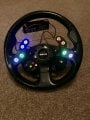
I have butchered my steering column stalks and fitted buttons and rotary switches on the steering wheel but I do have a couple of issues upon testing hence my plea for help.

I used 2 Pololu Pushbutton Power Switches to initiate the turn signals but upon fitting the wheel to my Toyota mr2 mk2 I only get a click and no flasher. Real head scratcher.
Power goes to the flasher but doesn’t turn on the lights.

Also utilised the wiper circuit board and modified it. But again on fit I have an issue. The wiper when selected is laboured and grinds to a halt when fast speed selected.

The pololu switch diagram is readily available on line and I will attach a couple of picks of the wiper circuit.

I fitted a 16 pin nato plug, one end goes to the loom the other to a clock spring. I shorted out the common pin to the left indicator and it flashes, same for right.

Thanks in advance of any help.

Regards

Dave
 

Reloadron

Joined Jan 15, 2015
7,857
The pololu switch diagram is readily available on line and I will attach a couple of picks of the wiper circuit.
Pictures and a schematic of what you have would go a long way in solving the problem(s). Less a drawing it is about impossible to suggest anything. :(

Ron
 

drc_567

Joined Dec 29, 2008
1,156
... diagram from an old Camry shows continuous power going to the flasher green with red stripe wire. From flasher to both turn signals ( a common connection point) there is a green with black stripe wire. The Left side switch output to the Left light is colored green with a black stripe. The Right side switch output to the Right light is colored green with a yellow stripe. The one remaining detail is to connect a white wire with a black stripe from the flasher to a chassis ground. The ground connection should probably be verified to have continuity with the negative battery terminal.

... need to compare this description to the wiring diagram that you have.
 

MisterBill2

Joined Jan 23, 2018
27,186
What was the reason for changing all of the stuff?? What problem was there with the original hardware?? That can provide a lot of insight as to why there are problems now. Most of the folks here are not mind readers, we need text, and diagrams, or at the very least, complete descriptions.
 

Thread Starter

Moose764

Joined Dec 29, 2018
23
Hi all
Thank you for your quick reply.
Sorry thought I had uploaded the diagrams.

Will do that now.

I guess in answer to why.... why not?
 

Thread Starter

Moose764

Joined Dec 29, 2018
23
77241719-9740-47E0-B814-ED1C0203EC5E.jpeg I soldered wires to the numbered solder points and connected them to a rotory switch. The sense is correct but as I said the wiper motor seems laboured
 

Thread Starter

Moose764

Joined Dec 29, 2018
23

Alec_t

Joined Sep 17, 2013
15,103
Power goes to the flasher but doesn’t turn on the lights.
As per the blurb on the Pololu site, the switches don't retain their state when the power input disappears and they usually power up in the 'off' state; so every flash would turn them off when wired as shown.

Edit:
Methinks you'll need a second flasher unit, so that the switches can be fed continuous input power and each can drive a respective flasher unit. A problem with that, though, is that the two flasher units wouldn't keep in phase, contrary to UK law at least.
 
Last edited:

Thread Starter

Moose764

Joined Dec 29, 2018
23
Well I thought perhaps a solonoid between the switch and flasher would prevent the flasher from turning off the switch, isolating it so to speak
 

MisterBill2

Joined Jan 23, 2018
27,186
You've lost me. What would the solenoids be doing?
I believe that "solenoids" in this case would be what I call relays. In which case yes, they would work. BUT that is making a complex system even more complex. And I am wondering if the vehicle is located in some country where repair parts are either not available, or cost six months pay. If there is not some failure then why change things? If the sole purpose is to put push-button controls on the wheel I suggest that is a waste of time and resources. Yes, it could be done, but it would not be worth the effort. And if it was really needed then a simpler approach would be actual solenoids to move the lever in response to the buttons being pushed.
 

Thread Starter

Moose764

Joined Dec 29, 2018
23
I tried to design it just using relays but couldn’t work out how to wire it up so that the left input would cancel the right and vise versa. Would you?
 

MisterBill2

Joined Jan 23, 2018
27,186
I tried to design it just using relays but couldn’t work out how to wire it up so that the left input would cancel the right and vise versa. Would you?
It is certainly possible to do the function with relays, but for cancelling I suggest that rather than use the opposite signal to cancel, that pressing and holding the same button for a few seconds should cause the cancellation. In addition, you need to have an automatic cancellation after making the turn, at least I think that should be part of the system. Next question is would the additions remove the original lever switch functions? or be in addition to the original functions? At this point, and with the complexity growing, a small PLC device from a company such as "Automation Direct" will probably be the very best choice for cost, simplicity, and reliability.
 

Thread Starter

Moose764

Joined Dec 29, 2018
23
ED89A795-C85A-4CB0-B84F-84F09C6D3DCD.jpeg 414F23EA-6580-4DBF-BE6A-D7ED2DA3E9F1.jpeg The system I am trying to build has been done already and is fitted to some Ferrari cars.

The same button will cancel it’s self and be cancelled by the opposite button also so you don’t have to make 2 selections whe changing direction. Believe me we have roundabouts in the uk and it requires a quick right then left selection sometimes.

I know you don’t like the idea but it’s a kit car, a toy so to speak and I’m having a play. I saw it on the Ferrari, liked it and wondered if I could do it. I’m an aircraft engineer with very limited electronics experience but I don’t think I’ve done too bad up to now.

All modern cars now have lots of steering wheel function buttons. I’ve taken the clock spring from a Mazda with 16 wires so all my buttons run through that down to the loom.

If you could just help me out with this I would be so great full. I miss driving the car.

I’ve spent a lot of time doing this so don’t really want to scrap it now.

I’ve uploaded some pics so you can see what I’ve already done.B067DA8A-DFFE-4101-8544-133793B0E423.jpegE73823BD-235E-4BF2-A81E-ECF6C9D457D0.jpeg


Regards

Dave
 

Reloadron

Joined Jan 15, 2015
7,857
Really pretty cool. :)

I think if we dig into it in any high end car we will find a micro-controller in the mix. I ride a 92 Harley Electroglide and while it does not use fuel injection it does have an ECU and it also has a turn signal control module which has several inputs including a speedometer input. The turn signals cancel after driving a preset distance or if I have the right signal on and hit my left turn signal the right cancels, and visa versa. They also cancel after a given time period. Turn signals, hazard lights all controlled by a small decision making module and that was 1992.

If you really want to play around with things like you shared in the picture you may want to get into playing around with micro-controllers and just simple basic kits. They can prove to be entertaining and enlightening little toys.

Ron
 

Thread Starter

Moose764

Joined Dec 29, 2018
23
Thanks Ron

Love Harley’s. I’ve seen the bike turn signal modules but they are a little pricey for me.

I’d love to get into micro controllers and maybe I will at some stage but I just want to get my car back on the road now.

Is there a chance you could help me out with a schematic for what I need to do without micro control.
 
Top