Help with Theremin oscillators

Thread Starter

eswara1997

Joined Dec 14, 2013
34
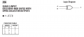
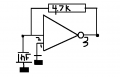
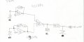
I am building a basic theremin device. I need it very sensitively however. I'm trying to use it to detect very slight changes in movement. I have currently created a TTl circuit. I have a fixed oscillator and a variable oscillator. My TTL chip is a 74LS132. The frequency from my variable oscllator is about 435 Khz and so is my fixed oscillator. My mixer is a 74ls266n chip. I used an am radio and was able to detect both signals. They're almost beating each other. I caught a harmonic at 860kHz.

The fixed frequency was very slight. What i mean is that unlike the variable, it was very difficult for me to detect. I had to use wet fingers on my capacitor to hear the change in the sound. For the variable i just had to touch the top of the capacitor to hear it change.

My question is - i'm receiving no frequencies from my "mixer." I'm assuming this is because the difference of two same frequencies will be 0. How can i make this whole circuit work so i can detect slight changes rather than having to actually touch the capacitors.
 

Attachments

Last edited:

Richie121

Joined Jan 12, 2014
27
Sorry I can't help with the technical (not my level yet) but I was impressed to see someone making one. Very iconic music from the sci-fi era.
 

MikeML

Joined Oct 2, 2009
5,444
I'll bet that what is happening is that the two oscillators are "injection locking" due to coupling in the power supply, common mode impedance along the ground, ground loop. This means that they are actually running at exactly the same frequency.

That is why you can only hear "one" in the radio.

You will have to go to extraordinary lengths to keep this from happening, including separate chips for the oscillators, separate voltage regulators, lots of bypass caps, shielding, etc.
 

bertus

Joined Apr 5, 2008
22,923
Hello,

The 266 is an open collector device.
This means that a resistor is needed to pull-up the output voltage.
The given resistor of 4k7 in your schematic is connected to ground.
Connecting this to the powersupply will provide the solution.


Bertus
 

Attachments

Last edited:

MrChips

Joined Oct 2, 2009
34,809
Yes. Instead of connecting the 4.7kΩ resistor to ground, connect it to +5V.
(Your drawing shows 3V which I presume is a mistake.)

Just curious why you are using a 74LS266 instead of the more common 74LS86.
(Note that the pinouts are not the same.)
 

Thread Starter

eswara1997

Joined Dec 14, 2013
34
well i tried 2 cmos 4093 and 4077 chips however they burned out after working one day. SO i switched to ttl chips because they are far more resistant. I just need a dang fixed oscillator to match up with the variable. I'm low on time till my science fair and need to get a theremin style oscillator circuit working.
 

alfacliff

Joined Dec 13, 2013
2,458
most of the theremin circuits I have seen use LC oscilators, by adjusting the inductance and capacitance you can make them very sensative to small changes in capacitance. or one crystal oscilator and one tuned circuit LC oscilator.
 

Thread Starter

eswara1997

Joined Dec 14, 2013
34
i don't have time to reconfigure my whole schematic. Additionally i believe lc circuits can't be used for lower frequencies. I'm on a tight budget and i've had to buy too many parts already.
So i constructed an oscillator based off the XNOR gate. It is very similar to the original fixed oscillator except for the fact that pin 1 is now grounded instead of positive. This is to compensate for the fact that now its an XNOR gate. However , the frequency that i have is way too high. I have it at about 2-3 megahertz based on my oscilloscope reading. My frequency counter does not measure that high frequencies. My variable oscillator is at 460 kHz. So i need to bring down my fixed oscillators. I'm unsure of how to do this. I tried increasing the capacitance to 1uF, but it didn't do much. So how can i decrease frequency?
 

Attachments

tubeguy

Joined Nov 3, 2012
1,157
Use a Schmitt trigger gate. It has hysteresis, so is better suited to making an oscillator of this type.
This type of gate turns on at about 2/3 Vcc and off at about 1/3 Vcc. So, the R/C circuit has a more definite period of time to charge/discharge
 
Last edited:

alfacliff

Joined Dec 13, 2013
2,458
with a capacitance of 1 mfd, how do you expect hand capacitance to vary the frequency of the oscilator? a few pf will not make very much difference.
 

Thread Starter

eswara1997

Joined Dec 14, 2013
34
so what value is ideal? I'm trying to detect as faint of a change as possible. Essentially detecting change in chest movement is what i'm trying to measure. So what value capacitance should i use.
 

tubeguy

Joined Nov 3, 2012
1,157
Can you post the schematic including the XNOR mixer?

I'm curious about the values for the R and C for the oscillator(s).
 
Top