Facebook
 Google
 GitHub
 Linkedin
Hi to all... I have been struggling in an arduino application, is a control board... and there is weeks when everything is all right... and weeks were the arduino make weird stuff... Now...
This is the original question;
http://forum.allaboutcircuits.com/threads/how-to-avoid-return-v-to-turn-led-on.104370/
I ask in the forum and the suggested answer was; Electrical Noise...
Makes a lot of sense... because the arduino is in a box turning on and off contactors, and depending of a voltage line that a lot of inductance and motor loads...
So today I add A couple of snubbers to the contactors... And I intend to do a filter for the VCC to arduino.
Currently the arduino gets its VCC from a switched power source (Like the old cellphone ones)... so no great signal stability...
There has been a strong recomendation to add multiple capacitors , between the power source and the arduino, to get less noise of the main line.
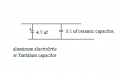
So today I buy 5 capacitors; 3300uf, 2200uf, 22uf, 1uf, 0.47uf...
And I start to make a schematic on Proteus 8, I want to know if this filter is good enough for futures applications add It at the controls as standard part.
However.. I dont know how to simulate something like this... is a AC generator? a signal generator? ??
Or more concrete... how can I see if the selected values will provide an signal stability for the Arduino, I know Im not giving any parameters.. but I trust some one in the forum, wise and good will provide us with a parameter.
Here is the file;
https://onedrive.live.com/redir?resid=6727EC83F4A63D75!255
Thanks for the suggestions.
Thanks in advance.
-Alex.
This is the original question;
http://forum.allaboutcircuits.com/threads/how-to-avoid-return-v-to-turn-led-on.104370/
I ask in the forum and the suggested answer was; Electrical Noise...
Makes a lot of sense... because the arduino is in a box turning on and off contactors, and depending of a voltage line that a lot of inductance and motor loads...
So today I add A couple of snubbers to the contactors... And I intend to do a filter for the VCC to arduino.
Currently the arduino gets its VCC from a switched power source (Like the old cellphone ones)... so no great signal stability...
There has been a strong recomendation to add multiple capacitors , between the power source and the arduino, to get less noise of the main line.
So today I buy 5 capacitors; 3300uf, 2200uf, 22uf, 1uf, 0.47uf...
And I start to make a schematic on Proteus 8, I want to know if this filter is good enough for futures applications add It at the controls as standard part.
However.. I dont know how to simulate something like this... is a AC generator? a signal generator? ??
Or more concrete... how can I see if the selected values will provide an signal stability for the Arduino, I know Im not giving any parameters.. but I trust some one in the forum, wise and good will provide us with a parameter.
Here is the file;
https://onedrive.live.com/redir?resid=6727EC83F4A63D75!255
Thanks for the suggestions.
Thanks in advance.
-Alex.