Facebook
 Google
 GitHub
 Linkedin
Hi all,
Ill try to make a long story short...
I'm making a welder called a pulse arc welder. Nothing very fancy about the power circuit of it, basically a 48v power supply, a large bank of capacitors in parallel equaling about 1/4 farad, and a bunch of mosfets in parallel acting as the switch.
The mechanical side consists of a brass collar which grounds to the two sheets to be welded and a tungsten electrode in the center which is lifted quickly during the weld via a solenoid.
Once the collar and electrode both make contact with the surface, an arduino begins a bunch of closely timed steps to lift the electrode and begin the weld.
I need help with a circuit that will detect when the electrode and brass collar both make and break contact with the metal to be welded and generates a ~5v "contact" signal the arduino will be able to read without frying everything once the hundreds of amps from the weld are dumped into the same wires.
Any help would be greatly appreciated, I'm no EE, just beginning to learn all this stuff.
Thanks a lot!!
-Charlie
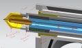
In the attachment:
Orange is the brass grounding head
Grey is the tungsten electrode
Red box is what id like to figure out.
P1 comes from a mosfet driver circuit
I do have some flyback diodes across the powersupply just didnt show them
Ill try to make a long story short...
I'm making a welder called a pulse arc welder. Nothing very fancy about the power circuit of it, basically a 48v power supply, a large bank of capacitors in parallel equaling about 1/4 farad, and a bunch of mosfets in parallel acting as the switch.
The mechanical side consists of a brass collar which grounds to the two sheets to be welded and a tungsten electrode in the center which is lifted quickly during the weld via a solenoid.
Once the collar and electrode both make contact with the surface, an arduino begins a bunch of closely timed steps to lift the electrode and begin the weld.
I need help with a circuit that will detect when the electrode and brass collar both make and break contact with the metal to be welded and generates a ~5v "contact" signal the arduino will be able to read without frying everything once the hundreds of amps from the weld are dumped into the same wires.
Any help would be greatly appreciated, I'm no EE, just beginning to learn all this stuff.
Thanks a lot!!
-Charlie
In the attachment:
Orange is the brass grounding head
Grey is the tungsten electrode
Red box is what id like to figure out.
P1 comes from a mosfet driver circuit
I do have some flyback diodes across the powersupply just didnt show them
Attachments
-
 44.7 KB Views: 15