Help with reading a signal with a microcontroller

philba

Joined Aug 17, 2017
959
Well, you could use an op amp (like a LM324 quad) and set the gain to exceed your input device's "min high" voltage. You might need to have the supply larger than 3.3V or use a "rail-to-rail" op amp. Could be done but seems a bit "rube goldbergesque".

I still think there is something not quite right here - I find it odd that the dropping resistors are remote from the LEDs.
 

Thread Starter

128ITSH

Joined Jul 20, 2017
101
Well, you could use an op amp (like a LM324 quad) and set the gain to exceed your input device's "min high" voltage. You might need to have the supply larger than 3.3V or use a "rail-to-rail" op amp. Could be done but seems a bit "rube goldbergesque".

I still think there is something not quite right here - I find it odd that the dropping resistors are remote from the LEDs.
Thanks for the help! I do have an LM741CN which is an op-amp, and the board which the led is running on is 5V. But how do I interface the amplifier to the LED/inputs?

This Air conditioner control board is quiet old so everything is odd for me here:D
 

LesJones

Joined Jan 8, 2017
4,509
Try connecting 2 LEDs in series for each LED position. If they still light then you could use opto isolators with the input side in series with the original LEDs

Les.
 

Thread Starter

128ITSH

Joined Jul 20, 2017
101
Look up "transistor as a switch".
Thanks, I did look at it before but its hard for me to calculate the base/emitter resistor values, can you please give the right values for me or a simple formula to get them? I have some 2N3904 NPN transistors.

Try connecting 2 LEDs in series for each LED position. If they still light then you could use opto isolators with the input side in series with the original LEDs
That looks like an interesting idea, and there is no need to drive two leds in series because I can pull the LEDs out of the circuit and connect an opto-isolator instead. but I will prefer using a transistor if its possible because I already have it unlike the opto-isolator
 

MrChips

Joined Oct 2, 2009
34,947
The voltages you have indicated make no sense.
It is possible that the LEDs are driven with a PWM signal.
You need to use an oscilloscope to verify what signal is used to drive the LED.
 

philba

Joined Aug 17, 2017
959
Thanks for the help! I do have an LM741CN which is an op-amp, and the board which the led is running on is 5V. But how do I interface the amplifier to the LED/inputs?

This Air conditioner control board is quiet old so everything is odd for me here:D
the 741 is pretty ancient and you will need one for each LED you want to monitor. I like the 358 as it has 4 op amps in one package, it also can get pretty close to zero off a single supply. Pretty cheap, too.

But, the suggestion of using opto isolators is good one and maybe be a cleaner solution. Even if they are driven by PWM like Mr Chips suggests, it should still work. In fact, if there isn't enough current to drive 2 LEDs, you can just replace the indicator LEDs with the optos and then on your interface board add an LED to give visual indication.
 

Thread Starter

128ITSH

Joined Jul 20, 2017
101
The voltages you have indicated make no sense.
It is possible that the LEDs are driven with a PWM signal.
You need to use an oscilloscope to verify what signal is used to drive the LED.
Thankes for the adice,this is very possible and I find these voltages very strange too.
Unfortunatly, I don't have an oscilloscope. is there an alternative for that? or can you advice me on a cheap one?

If I will not find a way to measure this signal, I will probably use the opto-isolator solution which is good for this scenario
 

Thread Starter

128ITSH

Joined Jul 20, 2017
101
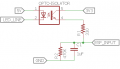
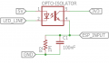
After buying an opto-isolator, and testing it with the esp8266 and the air conditioner - It turns out that the LED is powered with pwm signals. to verify this I looked at it from my smartphone camera and saw the filckering of the LED. So I tried using a RC low pass filter and it works! the pwm signals are changed to a stable "line". but I want a capacitor lower than 1uf because it is phisicaly too big for the enclosure. the way the filter is wired up is strange because I also want a pull-down resistor to the input. can you recommend me on a way to connect it better, but using a lower-value capacitor like 100nF.
 

Attachments

philba

Joined Aug 17, 2017
959
Shouldn't you have a current-limiting resistor on the opto's input?
Since that circuit is currently (pun semi intended) driving an LED that has yet to burn out, the presumption is that there is a limiting resistor somewhere at the other end of the cable so it should be ok as is.
 

Thread Starter

128ITSH

Joined Jul 20, 2017
101
By changing R1 to 0Ohm (not using it), R2 to 1MOhm and C to 100nf, the filter works (even thogh both resistor and capacitor are connected in parralel to ground). I will test it on the AC now.
 

Thread Starter

128ITSH

Joined Jul 20, 2017
101
It works! I can fully read if the 3 LED's are on or off using an opto-isolator and RC filter (even though the C and R are connected in parralel) .

Thanks alot to everyone who helped and guided me through this. Even though it wasn't such a comlicated issue, I don't know how I would do it myself without your help.
 

Attachments

Top