help with motion sensor circuit

Thread Starter

spidermanIIII

Joined Nov 22, 2013
78
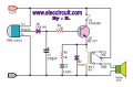
i searched for motion sensor circuit and i found this site here , i have some question what is the usage of the capacitor C1 and the site mentioned that this alarm will work for about 20 seconds how can he calculate time mathematically
 

wayneh

Joined Sep 9, 2010
17,498
The transistor cannot turn off until the voltage on C1 falls below the minimum hold voltage of the relay, plus about 0.6V. So if the relay lets go at 4V, it will do so when the base voltage dictated by C1 falls to 4.6V. C1 charges to 12 - 0.6V = 11.4V almost immediately upon a trigger, but it takes time to discharge because of the base resistor. I'm a little surprised it takes 20 seconds, but that's how it works.

You cannot really predict the time with much accuracy beforehand, since it will depend on the gain of the particular transistor, under its particular conditions (including temperature).
 

Thread Starter

spidermanIIII

Joined Nov 22, 2013
78
The transistor cannot turn off until the voltage on C1 falls below the minimum hold voltage of the relay, plus about 0.6V. So if the relay lets go at 4V, it will do so when the base voltage dictated by C1 falls to 4.6V. C1 charges to 12 - 0.6V = 11.4V almost immediately upon a trigger, but it takes time to discharge because of the base resistor. I'm a little surprised it takes 20 seconds, but that's how it works.

You cannot really predict the time with much accuracy beforehand, since it will depend on the gain of the particular transistor, under its particular conditions (including temperature).
what about RC is that can use in mathematical operation to calculate the delay
 

wayneh

Joined Sep 9, 2010
17,498
You're welcome to try! (By the way, LED 1 is backwards in that schematic.)

In a simple RC decay, which this is not, the solution would look like V2/V1 = 4.6/11.4 = exp(-RC/t). With the shown values, RC = 1200 x 220 x 10^-6 = 0.264s^-1. So the time would be only -0.264/ln(4.6/11.4) = 0.29 seconds.

But this is not a simple RC decay, it's an emitter-follower. The capacitor is not discharging to ground but rather to the voltage on top of the relay. That decay depends on the transistor gain which, as I said, is not easily predicted with accuracy. If you just need to get close, say within a 2x factor, you can estimate the gain. But then you'll need to know the current vs voltage for the relay coil.
 

Thread Starter

spidermanIIII

Joined Nov 22, 2013
78
You're welcome to try! (By the way, LED 1 is backwards in that schematic.)

In a simple RC decay, which this is not, the solution would look like V2/V1 = 4.6/11.4 = exp(-RC/t). With the shown values, RC = 1200 x 220 x 10^-6 = 0.264s^-1. So the time would be only -0.264/ln(4.6/11.4) = 0.29 seconds.

But this is not a simple RC decay, it's an emitter-follower. The capacitor is not discharging to ground but rather to the voltage on top of the relay. That decay depends on the transistor gain which, as I said, is not easily predicted with accuracy. If you just need to get close, say within a 2x factor, you can estimate the gain. But then you'll need to know the current vs voltage for the relay coil.
Ok what i understood from you that this is not simple RC because the capacitor should directly be connected to the ground to be simple RC is that correct . second thing what if i have the gain of transistor can you show me how to use it to calculate the time delay
 

MrCarlos

Joined Jan 2, 2010
400
Hello again spidermanIIII

It is very hard to calculate how long the relay will remain activated by the effect of the constant RC.

We can say that the value of R is the set of values:
- The impedance B-E of the transistor.
- The value or R for the LED & the impedance of the LED.
- The impedance of the relay coil.
- The actual value of the resistor R1.
But the B-E of transistor impedance varies in value as the current flowing through this junction.
Also the LED impedance.
Even knowing the transistor gain (Hfe) would be very difficult to calculate that time.

The time constant is, as we had already seen, the result of multiplying the value of R by the value of C.
In this case it would be 1200 X 0.000220 = 0.264 S = 264 mS.

That would be easier to measure time with an oscilloscope, as seen in the attached image.
It can be seen that the relay remains energized for a period of time of approximately 4.525 Seconds.
(Blue Line in Graph of XSC1).
The Red Line, in the graph, represents the charge and discharge of the capacitor.

It would be good that you take a look at the data sheets attached to you.
Especially parameter named Hfe.
You'll see it has a range. so the transistor you have in your hands: what gain has ??

For demonstration purposes I used an opto-sensor instead of PIR.
 

Attachments

Thread Starter

spidermanIIII

Joined Nov 22, 2013
78
Hello again spidermanIIII

It is very hard to calculate how long the relay will remain activated by the effect of the constant RC.

We can say that the value of R is the set of values:
- The impedance B-E of the transistor.
- The value or R for the LED & the impedance of the LED.
- The impedance of the relay coil.
- The actual value of the resistor R1.
But the B-E of transistor impedance varies in value as the current flowing through this junction.
Also the LED impedance.
Even knowing the transistor gain (Hfe) would be very difficult to calculate that time.

The time constant is, as we had already seen, the result of multiplying the value of R by the value of C.
In this case it would be 1200 X 0.000220 = 0.264 S = 264 mS.

That would be easier to measure time with an oscilloscope, as seen in the attached image.
It can be seen that the relay remains energized for a period of time of approximately 4.525 Seconds.
(Blue Line in Graph of XSC1).
The Red Line, in the graph, represents the charge and discharge of the capacitor.

It would be good that you take a look at the data sheets attached to you.
Especially parameter named Hfe.
You'll see it has a range. so the transistor you have in your hands: what gain has ??

For demonstration purposes I used an opto-sensor instead of PIR.
from datasheet you attached if Vce=1V and Ic=100mA the hfe varies from 100 to 630
 
Top