 Facebook
 Google
 GitHub
 Linkedin
Hello everyone,
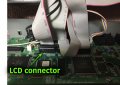
I bought a new VFD 1602 (7pin, 14 in total) for my synth but I can't make it work correctly. Although I connected all the pins in their place, I only see the characters randomly .
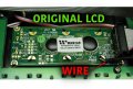
The original synth's LCD is 1602 (8pin, 16 in total) and behind it had one cable soldered that goes from it to the electronic board ( not sure if its a ground wire)
The curious thing is that, to see my VDF with the correct characters, I tried putting that "ground cable" over of the different pins until for my surprise something happened. The display worked fine!!
When I connected the wire to the pin 2 and turn ON the synth, nothing happened, but when I released it , the display became totally fine!
Like a on/off switch. But if I solder, is like being OFF again.
What am I doing wrong?
Thank you very much for the help and sorry of my english, I'm not native speaker.
I recorded a video where you can see , and upload pictures of the datasheet of the LCD and VFD.
Here's the link:
I bought a new VFD 1602 (7pin, 14 in total) for my synth but I can't make it work correctly. Although I connected all the pins in their place, I only see the characters randomly .
The original synth's LCD is 1602 (8pin, 16 in total) and behind it had one cable soldered that goes from it to the electronic board ( not sure if its a ground wire)
The curious thing is that, to see my VDF with the correct characters, I tried putting that "ground cable" over of the different pins until for my surprise something happened. The display worked fine!!
When I connected the wire to the pin 2 and turn ON the synth, nothing happened, but when I released it , the display became totally fine!
Like a on/off switch. But if I solder, is like being OFF again.
What am I doing wrong?
Thank you very much for the help and sorry of my english, I'm not native speaker.
I recorded a video where you can see , and upload pictures of the datasheet of the LCD and VFD.
Here's the link:
Attachments
-
 77.3 KB Views: 10
 -
 182.5 KB Views: 10


")


