Help with LCD change on my synth

Thread Starter

hide24

Joined Jul 9, 2019
84
Thank you MrChips,
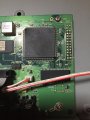
Yes, I turned off and on several times and the display works fine, but don’t show the correct characters unless I do the short circuit to the pin number 2 as I did in the video.
Is it very strange.

Could be the problem because the original LCD is 8 pin instead 7 (the new VFD)?

Also, seems that the connection is correct, the pins, everything seems OK, because if not when I do that procedure of the wire I guess I couldn’t see anything in the display right?
That wire needs to be connected somewhere perhaps?
 

Wolframore

Joined Jan 21, 2019
2,610
I think this is your problem...

the module does a power up and reset but if you have a slow power supply it is unable to reset correctly.

upload_2019-7-9_12-26-59.png

upload_2019-7-9_12-28-54.png

upload_2019-7-9_12-27-54.png
 

MrChips

Joined Oct 2, 2009
30,806
Edit: For TS, No.
@Wolframore and I are saying the same thing. The problem lies in power on reset.

Analyze the symptoms.

1) VFD does not work even when power is turned off and on again.
2) VFD works when you temporarily short pin-2 to GND. Note that pin-2 is Vcc power.

This means that the VFD is capable of working.
The interconnections are correct.
It has nothing to do with connections 2 x 7 versus 2 x 8. The additional two pins, pin-15 and pin-16 are for back-lighting of the LCD.

The only difference is pin-3 which is normally used for LCD contrast voltage.
On the VFD, it is used for /RST according to the information supplied in post #14.
According to your photo, JP1 is not bridged.

The question remains, does the information on post #14 with reference to JP1 accurate for your VFD? We don't know.
If this information applies to your VFD, then the problem has to do with the power ON reset sequence or with the initialization procedure.

The key information to take away here is that the VFD works after momentarily shorting the power connection to GND.
(Let me think about this a bit longer.)
 

Wolframore

Joined Jan 21, 2019
2,610
I'm guessing the power supply takes too long to charge up. It needs to be gated so it turn on after warm up. Otherwise it needs a reset command after powering up.
 

MrChips

Joined Oct 2, 2009
30,806
Question #1 - What state is the VFD in after /RST is applied? Is it in a state ready to accept commands and data even though it was not properly initialized by the MCU?

Question #2 - Why does VFD work after temporarily grounding Vcc? Isn't this the same as a power on reset?
In normal power-on versus shorting Vcc to GND, what is the power up sequence? Does the VFD power up before the MCU or vice versa?

It would appear that on normal power-on, the MCU is starting before the VFD gets a chance to startup.
 

Thread Starter

hide24

Joined Jul 9, 2019
84
Thank you very much,
I'm complete beginner with electronics and still some terms are unknown for me .
One thing I don't understand is about the "JP1", the jumper.
Is the little rubber that hold the pins? or is something like this? (photo)

#1 - The state after the RST ( I guess is RESET after the short) is completely fine, can receive commands when I use the knobs for change the parameters, and it works perfect.

#2 - That is what I'm wondering too.
it's exactly the same the reset with the switch than make the short circuit.
MrChips, maybe you're right. Seems that the MCU or at least the leds of the synth turn on before the display (but I can't make it sure 100% because is small miliseconds.)
I will try changing the power supply of the synth now for another if it happens the same.
 

Attachments

Last edited:

MrChips

Joined Oct 2, 2009
30,806
How do you change the power supply? I suppose it is a power adapter?

What is the make and model number of the synth?
Do you have its circuit schematics?
 

Thread Starter

hide24

Joined Jul 9, 2019
84
Sorry, I mean the power adapter.
The synth is an AKAI MINIAK.
I think the Alesis Micron it’s exactly the same synth build inside.
I’ll try to find now ;)
Thanks!
 

MrChips

Joined Oct 2, 2009
30,806
Look at the datasheet info supplied by @Wolframore in post #22.

I believe what they meant to say was:

7.5 Slow starting power supply may cause non-operation because on-chip microcomputer won't be reset.

Also the timing diagram (from my datasheet) seem to suggest that after Vcc is applied you need a minimum of 100μs before you can start writing to the VFD controller.

It would appear that the synth controller is starting up before the VFD module. It seems that you will have to do a fair bit of hardware hacking on the synth to get the VFD to work.

Is there a reason why you want to replace the LCD with the VFD module?
 

Thread Starter

hide24

Joined Jul 9, 2019
84
Well, mainly because the VFD is very bright and easy to see, specially for gigs. The other LCD was kind a blue with dark characters.

Would be very difficult to set the hardware hacking?
This only happens in this synth, or any synth I want to replace the LCD for a VFD?
Thank you!
 

MrChips

Joined Oct 2, 2009
30,806
If you look at page 32 of the Service Manual you will see a RESET switch with a device designator S1. Page 37 shows the location of the RESET switch on the synth circuit board (top left corner).

Presumably this switch is not installed on the board. If you momentarily short the pads where the switch ought to be while the power is ON it should reset your synth processor. This should restart the synth and perhaps will fix the VFD problem.

If this gets the VFD working we can then apply a hardware hack.
The simple solution would be to install a RESET push button which you can manually activate from outside of the synth case.

Alesis Micron RESET Schematics.jpg

Alesis Micron RESET Board Layout.jpg
 

Thread Starter

hide24

Joined Jul 9, 2019
84
Thank you very much. I never thought could be too difficult wow!
I'm watching the page 37 but it's not written where I should solder the reset button. Could you please tell me which place is ?
Also the reset button I should buy is something like this? (photo)
 

Attachments

MrChips

Joined Oct 2, 2009
30,806
Firstly, I don't yet know if this will fix your problem until you try it. Don't buy a switch yet.

On page 37 (bottom image on post #33), the S1 RESET button is located at the top left corner, where it says "micron analog modeling synth".

If you can locate this on your synth board, take clearly focused photos of top and bottom side of that corner and I will take it from there.
 

Wolframore

Joined Jan 21, 2019
2,610
It would be interesting to design a single stable one shot circuit with a capacitor delay to trigger after power up for the reset.
 

Thread Starter

hide24

Joined Jul 9, 2019
84
Thanks!! I found it!!
I upload the photo too, and I have marked with a circle, just where is the reset .
One doubt I have about the reset button is...Should I reset everytime I turn on the synth? or how it works exactly?
 

Attachments

MrChips

Joined Oct 2, 2009
30,806
One doubt I have about the reset button is...Should I reset everytime I turn on the synth? or how it works exactly?
Let's worry about that after we see if it works.

With the power ON, with a short piece of conducting wire (e.g. a paper clip) momentarily jumper across two pads at the S1 RESET switch, (two pads in a vertical line).
 

Thread Starter

hide24

Joined Jul 9, 2019
84
I just tried now with a paper clip and seems that turns OFF the synth and turn on again but the display only change characters randomly.
In a while I'm going to upload a video to see if I did it correclty.
 
Top