Help with I2C between pic 16f690 and LCD I2C interfase LCM1602

Thread Starter

Cristian Cox

Joined May 13, 2017
18
Hello all:
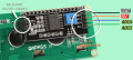
I am trying to connect a 16f690 pic with a LCD I2C interfase(LCM1602)
I only know some assembly but not C


Do you have any sugestion or at least an example how to establish communication between master (PIC) and slave (LCD interfase LCM1602 )?
There are some code in C, but if you have something in Assembly I would apreciate it.

I have read some I2C theory but I really need a push on this, I mean to write the code and of course to understand it first.
There are registers that need to be configured and I get lost on this.


Most of the example in internet are refered to Arduino, and they already come with the code for the LCD display.
I want to use my own code for the comuniccation between master and slave.

Thanks in advance if you can give me a hand

regards

Cristian
 

jpanhalt

Joined Jan 18, 2008
11,087
That is an ambitious project. The 16F690 is not an enhanced mid-range device, and AN734C has been updated to that class of chip, namely the 16F1937. Here is my bibliography from a couple of years ago. It is not complete and not all links are there. The application notes in C were of no interest to me.

Microchip:
AN1488 Bit bangged C code
AN1355 PIC18F
AN1302 C code
AN976 Chris Parris Assembly, 16F877A,uses MSSP, no interrupts, 02/01/2005 Pretty good
AN989 Chris Parris Assembly, 18F452, uses MSSP, no interrupts,05/09/2005 (http://ww1.microchip.com/downloads/en/AppNotes/00989A.pdf )
AN845 Craig King Assembly, 16F876, uses MSSP, no interrupts, polls PIR1,SSPIF 06/26/2002 Pretty good
AN734C Chris Best Assembly, 16F1937, uses MSSP, interrupts (https://www.microchip.com/wwwAppNotes/AppNotes.aspx?
appnote=en011798 )

Maxim:
AN3921 (https://www.maximintegrated.com/en/app-notes/index.mvp/id/3921 ) uses 16F628 , no interrupts, polling.

The version I ended up using had interrupts and ran on the 16F1829 (enhanced mid-range). The questions for you are:
1) Do you have to use that chip? Converting enhanced mid-range to it is not difficult, but it is easier not to have to do that. Main differences in this application are bank switching, indirect addressing (if used), and interrupt context saving.
2) Do you want to use interrupts or polling? Have you experience with either?
3) Do you want to bit bang or use the hardware interface (I assume the latter)?

Do you have a link to the datasheet for the LCM1602? Does it require the user to write the initialization? Is it readable or just writable?
 

Thread Starter

Cristian Cox

Joined May 13, 2017
18
That is an ambitious project. The 16F690 is not an enhanced mid-range device, and AN734C has been updated to that class of chip, namely the 16F1937. Here is my bibliography from a couple of years ago. It is not complete and not all links are there. The application notes in C were of no interest to me.

Microchip:
AN1488 Bit bangged C code
AN1355 PIC18F
AN1302 C code
AN976 Chris Parris Assembly, 16F877A,uses MSSP, no interrupts, 02/01/2005 Pretty good
AN989 Chris Parris Assembly, 18F452, uses MSSP, no interrupts,05/09/2005 (http://ww1.microchip.com/downloads/en/AppNotes/00989A.pdf )
AN845 Craig King Assembly, 16F876, uses MSSP, no interrupts, polls PIR1,SSPIF 06/26/2002 Pretty good
AN734C Chris Best Assembly, 16F1937, uses MSSP, interrupts (https://www.microchip.com/wwwAppNotes/AppNotes.aspx?
appnote=en011798 )

Maxim:
AN3921 (https://www.maximintegrated.com/en/app-notes/index.mvp/id/3921 ) uses 16F628 , no interrupts, polling.

The version I ended up using had interrupts and ran on the 16F1829 (enhanced mid-range). The questions for you are:
1) Do you have to use that chip? Converting enhanced mid-range to it is not difficult, but it is easier not to have to do that. Main differences in this application are bank switching, indirect addressing (if used), and interrupt context saving.
2) Do you want to use interrupts or polling? Have you experience with either?
3) Do you want to bit bang or use the hardware interface (I assume the latter)?

Do you have a link to the datasheet for the LCM1602? Does it require the user to write the initialization? Is it readable or just writable?
Thanks for the help I Will analyse the information you sent.
It looks I am pretty far from your knlowledge since mine is basic. I am trying to design a machine controlled by 16f690 and since I had 16f690 available, and since I need to sabe ports pins, I need the I2C comunication modality. I never thought it was, at least for me, complex to implement from scratch a communication between pic and the I2c interfase.
Yes I have data sheets of all components, it is just a matter how to put all the info together and implement something that Works.

thanks
 

jpanhalt

Joined Jan 18, 2008
11,087
If you have I2C working, that is probably the biggest hurdle. Here is some code I posted here: https://forum.allaboutcircuits.com/threads/fixing-the-sparkfun-4x20-lcd-display.148893/

Forget about all the interrupt stuff and just go the the initialization part (where I set up the processor. The subroutines are in the HD44780 LCD Routines section. That is, assuming your display driver is the Hitachi or a compatible version. I read the busy flag, but many people just insert a 40 us delay instead of the WNB routine. Of course, you will have to substitute the proper codes to set up a 16x2 display. If you have problems, I have rough code for that display too. Basically,all you have are some waits, put commands (PutCmd) and put characters (PutChar), no PutNib.

If you have problems, I will try to dust off the 8-bit parallel version I have for a 16x2 display I did awhile back.
 

jpanhalt

Joined Jan 18, 2008
11,087
@Cristian Cox
I had to run into town and realized immediately almost everything I have suggested so far is irrelevant assuming you have I2C running. Since the display almost certainly has its own processor in addition to the display controller, then there is a high likelihood it initialized itself (just like the unmodified SparkFun display does). What you need to dig up are whether any special control codes are used. For example, the unmodified SF display is quite unique. I have some backpacks from eBay that allow 1-wire serial, SPI, and I2C. They also have their own control codes.

Of course, nothing will be lost by sending an ascii character code and see whether it displays.

John
 

Thread Starter

Cristian Cox

Joined May 13, 2017
18
@Cristian Cox
I had to run into town and realized immediately almost everything I have suggested so far is irrelevant assuming you have I2C running. Since the display almost certainly has its own processor in addition to the display controller, then there is a high likelihood it initialized itself (just like the unmodified SparkFun display does). What you need to dig up are whether any special control codes are used. For example, the unmodified SF display is quite unique. I have some backpacks from eBay that allow 1-wire serial, SPI, and I2C. They also have their own control codes.

Of course, nothing will be lost by sending an ascii character code and see whether it displays.

John

Thanks a lot John for all the info

I Will try your advices

regards

Cristian
 

MMcLaren

Joined Feb 14, 2010
861
We haven't heard back from Cristian but I've been workin' on an assembly language demo for 16F690 with bit-banged I2C drivers for the relatively common Chinese PCF8574 based I2C LCD backpacks and HD44780 type LCD displays. The 16F690 is using the 8-MHz INTOSC and the I2C clock is 100-kHz (the PCF8574 limit). I'd be happy to share the program, if anyone is interested, but it's pretty crude and I still need to test it on real hardware. Anyway, here's a few excerpts (using some simple macros to hopefully improve readability). Suggestions and criticism welcomed.

Cheerful regards, Mike
Code:
;
;  setup I2C interface, scl = RC0, sda = RC1
;
        bsf     STATUS,RP0      ; bank 1                          |B1
        bsf     iic_tris,sclndx ; make scl pin (RC0) input        |B1
        bsf     iic_tris,sdandx ; make sda pin (RC1) input        |B1
        bcf     STATUS,RP0      ; bank 0                          |B0
        bcf     iic_port,sclndx ; scl output latch = 0            |B0
        bcf     iic_port,sdandx ; sda output latch = 0            |00
;
;  LCD "initialize by instruction" procedure for 4-bit interface
;
        DelayCy(30*msecs)       ; delay 30-msecs after power up   |B0
        putNyb (0x30)           ; function set: 8-bit             |B0
        DelayCy(5*msecs)        ; required 5-msec delay           |B0
        putNyb (0x30)           ; function set: 8-bit             |B0
;       DelayCy(160*usecs)      ; required 160-usec delay         |B0
        putNyb (0x30)           ; function set: 8-bit             |B0
;       DelayCy(160*usecs)      ; required 160-usec delay         |B0
        putNyb (0x20)           ; function set: 4-bit             |B0
;       DelayCy(160*usecs)      ; required 160-usec delay         |B0
;
;  now we're in 4-bit mode and can handle 8-bit transactions
;
        putCmd (0x28)           ; 4-bit, 2-lines, 5x7 font        |B0
        putCmd (0x08)           ; display, cursor, blink all off  |B0
        putCmd (0x01)           ; clear display                   |B0
        DelayCy(1530*usecs)     ; required 1.53-msec delay        |B0
        putCmd (0x06)           ; cursor inc, shift off           |B0
        putCmd (0x0C)           ; display on, leave cursor off    |B0
Code:
;******************************************************************
;  LCD functions                                                  *
;******************************************************************

lcdCmd                          ; entry point for "cmd" data
        clrf    rsflag          ; RS = 0 (command)                |B0
        skpz                    ; skip                            |B0
lcdDat                          ; entry point for "dat" data
        bsf     rsflag,0        ; RS = 1 (data)                   |B0
        call    lcdNyb          ; send hi nybble                  |B0
        swapf   workvar,W       ; send lo nybble                  |B0
;
;  ~~ 'lcdNyb' sequence ~~~~~~~~~      ~~< PCF8574 format >~~~
;  () I2C 'start' + I2C 'address'      P0(b0) -> LCD 'RS'
;  () write nibble, E = 1              P1(b1) -> LCD 'RW' (0)
;  () write nibble, E = 0              P2(b2) -> LCD 'E'
;  () I2C 'stop'                       P3(b3) -> LCD Backlight
;                                      P4(b4) -> LCD 'D4'
;   ~623-usecs (isochronous) for       P5(b5) -> LCD 'D5'
;   each lcdCmd and lcdDat call.       P6(b6) -> LCD 'D6'
;                                      P7(b7) -> LCD 'D7'
lcdNyb
        movwf   workvar         ; save temporarily                |B0
        movlw   0x4E            ; PCF8574 I2C address + 0 (wr)    |B0
        call    iic_start       ; I2C 'start' + 'address' + 'rw'  |B0
        movf    workvar,W       ;                                 |B0
        andlw   0xF0            ; use left nybble (b7..b4) bits   |B0
        btfsc   rsflag,0        ; RS = 0? yes, skip, else         |B0
        iorlw   b'00000001'     ; RS(b0) = 1                      |B0
        iorlw   b'00001100'     ; Backlight(b3) = 1, E(b2) = 1    |B0
        call    iic_write       ; data + bl, en, rw, rs bits      |B0
        xorlw   b'00000100'     ; clr E bit (b2)                  |B0
        call    iic_write       ; data + bl, en, rw, rs bits      |B0
        goto    iic_stop        ; I2C 'stop'                      |B0
Code:
;~~~~~~~~~~~~~~~~~~~~~~~~~~~~~~~~~~~~~~~~~~~~~~~~~~~~~~~~~~~~~~~~~~
;  I2C 'Start' condition.
;
iic_start
        scl(1)                  ; assure 'idle' condition         |B1
        sda(1)                  ;  "                              |B1
        sda(0)                  ; sda = 0                         |B1
        scl(0)                  ; scl = 0                         |B1
;       bcf     STATUS,RP0      ; bank 0                          |B0
;       return                  ;                                 |B0

;~~~~~~~~~~~~~~~~~~~~~~~~~~~~~~~~~~~~~~~~~~~~~~~~~~~~~~~~~~~~~~~~~~
;  I2C 'Write' byte.  maintain 10 cycles (5.0-us) between SCL
;  pin transitions for a 100-kHz I2C clock rate.
;
;                 194 cycles (97.0-us), including call & return
iic_write
        movwf   payload         ;                                 |
        movlw   8               ;                                 |
        movwf   bitctr          ;                                 |
sendbit
        scl(0)                  ; scl = 0                         |B1
        movf    iic_tris,W      ;                                 |B1
        iorlw   1<<sdandx       ; sda = 1                         |B1
        btfss   payload,7       ; msb = 1? yes, skip, else        |B1
        xorlw   1<<sdandx       ; sda = 0                         |B1
        movwf   iic_tris        ;                                 |B1
        scl(1)                  ; scl = 1                         |B1
        rlf     payload,W       ; payload <<= 1                   |B1
        rlf     payload,F       ;  "                              |B1
        decfsz  bitctr,F        ; done? yes, skip, else           |B1
        goto    sendbit         ; branch (send next bit)          |B1
        nop                     ;                                 |B1
        scl(0)                  ; scl = 0                         |B1
        sda(1)                  ; sda = 1 (hi-z input)            |B1
        scl(1)                  ; scl = 1 (9th clock)             |B1
        nop                     ; test for 'ACK' here ???         |B1
        movf    PCL,F           ; burn off 2 cycles               |B1
        movf    PCL,F           ; burn off 2 cycles               |B1
        scl(0)                  ; scl = 0                         |B1
        movf    payload,W       ; return wreg = payload           |B1
        bcf     STATUS,RP0      ; bank 0                          |B0
        return                  ;                                 |B0

;~~~~~~~~~~~~~~~~~~~~~~~~~~~~~~~~~~~~~~~~~~~~~~~~~~~~~~~~~~~~~~~~~~
;  I2C 'Stop' condition.
;
iic_stop
        sda(0)                  ; sda = 0                         |B1
        scl(1)                  ; scl = 1                         |B1
        sda(1)                  ; sda = 1                         |B1
        bcf     STATUS,RP0      ; bank 0                          |B0
        return                  ;                                 |B0
 
Last edited:

Thread Starter

Cristian Cox

Joined May 13, 2017
18
Dear Mike, thanks a lot for the help.
I have been disconnected since my mother passed away (but she is happy now and she left us with the example of enjoy in life).

I Will check with calm your script, and yes I am using an I2C "backpack" attached to an HD44780 type LCD display.


Thanks a lot and I Will comeback probably with questions

best regards

Cristian
 

MMcLaren

Joined Feb 14, 2010
861
Cristian.

The bit-banged I2C demo' for PCF8574 LCD backpack is now running on real hardware. If you'd like, I'll post the program after tidying it up a bit. In it's current form, it uses about 166 words of program memory and four bytes of RAM and provides only I2C 'start', 'stop', and 'write' functions (just enough to drive the PCF8574 backpack) as well as LCD 'init', 'putCmd', and 'putData' functions.

Cheerful regards, Mike, K8LH

Bit-Banged I2C.png
 
Last edited:

MMcLaren

Joined Feb 14, 2010
861
Attached, please find an example assembly language program for bit-banging low-level I2C start, write, and stop functions for PIC devices that do not have an MSSP I2C. The program is rather crude and pretty much the bare-bones minimum necessary to drive a PCF8574 I2C LCD backpack and HD44780 display (using 172 words of program memory).

The 16F690 target is using the 8-MHz INTOSC and generates a 100-kHz I2C clock. Low-level LCD init, putCmd, and putDat functions support the 'backpack' and display. It takes ~617-us to write a byte of data to the LCD so throughput is equivalent to almost 13000 baud.

Please note that while the picture shows a pair of pull-up resistors, I have since removed them after discovering that the backpack contains two 4.7K pull-ups.

Have fun... Please let me know if you have any questions...

Cheerful regards, Mike, K8LH


Here's one of the schematics I found that seems to match the PCF8574 based I2C LCD backpacks;

I2C LCD Backpack Schematic.png
 

Attachments

Last edited:

Thread Starter

Cristian Cox

Joined May 13, 2017
18
Mike, I have returned to the tracks
and I really apreciate your help with the 16f690 I2C example.
I am working right now understanding it.

I will let you know for questions

best regards

Cristian


Attached, please find an example assembly language program for bit-banging low-level I2C start, write, and stop functions for PIC devices that do not have an MSSP I2C. The program is rather crude and pretty much the bare-bones minimum necessary to drive a PCF8574 I2C LCD backpack and HD44780 display (using 172 words of program memory).

The 16F690 target is using the 8-MHz INTOSC and generates a 100-kHz I2C clock. Low-level LCD init, putCmd, and putDat functions support the 'backpack' and display. It takes ~617-us to write a byte of data to the LCD so throughput is equivalent to almost 13000 baud.

Please note that while the picture shows a pair of pull-up resistors, I have since removed them after discovering that the backpack contains two 4.7K pull-ups.

Have fun... Please let me know if you have any questions...

Cheerful regards, Mike, K8LH


Here's one of the schematics I found that seems to match the PCF8574 based I2C LCD backpacks;

View attachment 157445
 

Thread Starter

Cristian Cox

Joined May 13, 2017
18
Dear Mike:

I have been compiling your code the one that you helped last year for a I2C protocol applied to a 16f690 and display.

In the middle of compiling process I get this error in line 90.

I am using (tabs=8) Target Device: 16F690 *
(absolute mode)

but my Mpasm is 5.77, higher than yours (I dont see a problem on that)

I read that it might be something with the tabs and spaces?

do you have iany idea?

regards

Cristian


upload_2019-5-25_9-26-50.png


Code:
;******************************************************************
;                                                                 *
;   Filename: 16F690_LCD_I2C_Backpack_x2.asm                      *
;     Author: Mike McLaren, K8LH                                  *
;    (C)2018: Micro Applications Consultants                      *
;       Date: 31-Jul-2018                                         *
;                                                                 *
;                                                                 *
;   16F690 bit-banged I2C demo for PCF8574 I2C LCD Backpack and   *
;   HD44780 type LCD display.  Only basic I2C 'start', 'write',   *
;   and 'stop' routines included (enough to drive the backpack)   *
;   as well as LCD 'init', 'putCmd', and 'putDat' routines.       *
;                                                                 *
;                                                                 *
;      MPLab: 8.92    (tabs=8)          Target Device: 16F690     *
;      MPAsm: 5.51    (absolute mode)                             *
;                                                                 *
;******************************************************************
#include <P16F690.INC>
list st=off
errorlevel -302
radix dec

__config _FCMEN_OFF& _IESO_OFF& _MCLRE_OFF& _WDT_OFF& _INTOSCIO

;  _FCMEN_OFF           ; -- fail safe clock monitor enable off
;  _IESO_OFF            ; -- int/ext switch over enable off
;  _BOR_ON              ; default, brown out reset on
;  _CPD_OFF             ; default, data eeprom protection off
;  _CP_OFF              ; default, program code protection off
;  _MCLR_OFF            ; -- use MCLR pin as digital input
;  _PWRTE_OFF           ; default, power up timer off
;  _WDT_OFF             ; -- watch dog timer off
;  _INTOSCIO            ; -- internal osc, OSC1 and OSC2 I/O

;~~~~~~~~~~~~~~~~~~~~~~~~~~~~~~~~~~~~~~~~~~~~~~~~~~~~~~~~~~~~~~~~~~
;  variables
;
cblock  0x20
workvar                         ; putCmd(), putDat(), putNyb()
endc
cblock  0x70
loopctr                         ; iic_write()
payload                         ; iic_write()
delayhi                         ; DelayCy() subsystem variable
endc
rsflag  equ delayhi         ; putCmd(), putDat(), putNyb()

;~~~~~~~~~~~~~~~~~~~~~~~~~~~~~~~~~~~~~~~~~~~~~~~~~~~~~~~~~~~~~~~~~~
;  define 'scl' and 'sda' port and pins
;
iic_tris equ    TRISC           ; TRIS reg for scl pin
iic_port equ    PORTC           ; PORT reg for scl pin
sclndx   equ     RC0             ; index for scl pin (RC0)
sdandx   equ     RC1             ; index for sda pin (RC1)
;
;  LCD DDRAM address constants
;
line1   equ     128+0           ; LCD "line 1" command
line2   equ     128+64          ; LCD "line 2" command

;~~~~~~~~~~~~~~~~~~~~~~~~~~~~~~~~~~~~~~~~~~~~~~~~~~~~~~~~~~~~~~~~~~
;  LCD helper macros
;
putNyb  macro   param           ;
        movlw   param           ;                                 |B0
        call    lcdNyb          ;                                 |B0
        endm

putCmd  macro   param           ;
        movlw   param           ;                                 |B0
        call    lcdCmd          ;                                 |B0
        endm

putDat  macro   param           ;
        movlw   param           ;                                 |B0
        call    lcdDat          ;                                 |B0
        endm

;~~~~~~~~~~~~~~~~~~~~~~~~~~~~~~~~~~~~~~~~~~~~~~~~~~~~~~~~~~~~~~~~~~
;  K8LH DelayCy() subsystem macro generates four instructions      ~
;~~~~~~~~~~~~~~~~~~~~~~~~~~~~~~~~~~~~~~~~~~~~~~~~~~~~~~~~~~~~~~~~~~
        radix dec
clock   equ     8               ; 4, 8, 12, 16, 20 (MHz), etc.
usecs   equ     clock/4         ; cycles/microsecond multiplier
msecs   equ     usecs*1000      ; cycles/millisecond multiplier
dloop   equ     5               ; loop size, 5 to 8 cycles
;
;  -- loop --  -- delay range --  -- memory overhead ----------
;  5-cyc loop, 11..327690 cycles,  9 words (+4 each macro call)
;  6-cyc loop, 11..393226 cycles, 10 words (+4 each macro call)
;  7-cyc loop, 11..458762 cycles, 11 words (+4 each macro call)
;  8-cyc loop, 11..524298 cycles, 12 words (+4 each macro call)
;
DelayCy macro   cycles          ; range, see above
    if (cycles<11)|(cycles>(dloop*65536+10))
        error " DelayCy range error "
    else
        movlw   high((cycles-11)/dloop)+1
        movwf   delayhi
        movlw   low ((cycles-11)/dloop)
;       rcall   uLoop-(((cycles-11)%dloop)*2)    ; (18F version)
        call    uLoop-((cycles-11)%dloop)        ; (16F version)
    endif
        endm

;******************************************************************
;  reset vector                                                   *
;******************************************************************
        org     0x000
v_res
        clrf    STATUS          ; force bank 0 and IRP = 0        |B0
        goto    setup           ;                                 |B0

;******************************************************************
;  interrupt vector                                               *
;******************************************************************
        org     0x004
v_irq

;******************************************************************
;  main setup                                                     *
;******************************************************************

setup
        bcf     STATUS,RP0      ;                                 |
        bsf     STATUS,RP1      ; bank 2                          |B2
        clrf    ANSEL           ; turn off analog pin functions   |B2
        clrf    ANSELH          ;                                 |B2
        bcf     STATUS,RP1      ; bank 0                          |B0
        bsf     STATUS,RP0      ; bank 1                          |B1

        movlw   b'01110000'     ; setup INTOSC for 8-MHz          |B1
        movwf   OSCCON          ;                                 |B1
        btfss   OSCCON,HTS      ; osc stable? yes, skip, else     |B1
        goto    $-1             ; test again                      |B1

        clrf    TRISC           ; RC5..RC0 all outputs            |B1
        clrf    TRISB           ; RB7..RB4 all outputs            |B1
        clrf    TRISA           ; all outputs, except RA3         |B1
        bcf     STATUS,RP0      ; bank 0                          |B0
        clrf    PORTC           ;                                 |B0
        clrf    PORTB           ;                                 |B0
;
;  setup I2C interface, scl = RC0, sda = RC1
;
        bsf     STATUS,RP0      ; bank 1                          |B1
        bsf     iic_tris,sclndx ; make scl pin input              |B1
        bsf     iic_tris,sdandx ; make sda pin input              |B1
        bcf     STATUS,RP0      ; bank 0                          |B0
;       bcf     iic_port,sclndx ; scl output latch = 0            |B0
;       bcf     iic_port,sdandx ; sda output latch = 0            |B0
;
;  LCD "initialize by instruction" procedure for 4-bit interface
;
test
        DelayCy(30*msecs)       ; delay 30-msecs after power up   |B0
        putNyb (0x30)           ; function set: 8-bit             |B0
        DelayCy(5*msecs)        ; required 5-msec delay           |B0
        putNyb (0x30)           ; function set: 8-bit             |B0
;  n/a  DelayCy(160*usecs)      ; required 160-usec delay         |B0
        putNyb (0x30)           ; function set: 8-bit             |B0
;  n/a  DelayCy(160*usecs)      ; required 160-usec delay         |B0
        putNyb (0x20)           ; function set: 4-bit             |B0
;  n/a  DelayCy(160*usecs)      ; required 160-usec delay         |B0
;
;  now we're in 4-bit mode and can handle 8-bit transactions by
;  sending both hi & lo nibbles using putCmd & putDat macros.
;
        putCmd (0x28)           ; 4-bit, 2-lines, 5x7 font        |B0
        putCmd (0x08)           ; display, cursor, blink all off  |B0
        putCmd (0x01)           ; clear display                   |B0
        DelayCy(1530*usecs)     ; required 1.53-msec delay        |B0
        putCmd (0x06)           ; cursor inc, shift off           |B0
        putCmd (0x0C)           ; display on, leave cursor off    |B0

;******************************************************************
;  main loop                                                      *
;******************************************************************

loop
        putCmd (line1+2)        ; LCD line 1, column 3            |B0
        putDat ('H')            ;                                 |B0
        putDat ('e')            ;                                 |B0
        putDat ('l')            ;                                 |B0
        putDat ('l')            ;                                 |B0
        putDat ('o')            ;                                 |B0
        putDat (' ')            ;                                 |B0
        putDat ('W')            ;                                 |B0
        putDat ('o')            ;                                 |B0
        putDat ('r')            ;                                 |B0
        putDat ('l')            ;                                 |B0
        putDat ('d')            ;                                 |B0
        putDat ('!')            ;                                 |B0

        goto    $               ;

;~~~~~~~~~~~~~~~~~~~~~~~~~~~~~~~~~~~~~~~~~~~~~~~~~~~~~~~~~~~~~~~~~~
;  low-level LCD drivers for PCF8574 based I2C LCD backpack       ~
;~~~~~~~~~~~~~~~~~~~~~~~~~~~~~~~~~~~~~~~~~~~~~~~~~~~~~~~~~~~~~~~~~~

lcdCmd                          ; entry point for "cmd" data
        clrf    rsflag          ; wreg = data, RS = 0 (cmd)       |B0
        skpz                    ; skip                            |B0
lcdDat                          ; entry point for "dat" data
        bsf     rsflag,0        ; wreg = data, RS = 1 (data)      |B0
        call    lcdNyb          ; send hi nybble                  |B0
        swapf   workvar,W       ; send lo nybble                  |B0
;
;  ~~ 'lcdNyb' sequence ~~~~~~~~~      ~~< PCF8574 format >~~~
;  () I2C 'start' + I2C 'address'      P0(b0) -> LCD 'RS'
;  () write nibble, E = 1              P1(b1) -> LCD 'RW' (0)
;  () write nibble, E = 0              P2(b2) -> LCD 'E'
;  () I2C 'stop'                       P3(b3) -> LCD Backlight
;                                      P4(b4) -> LCD 'D4'
;   ~617-usecs (isochronous) for       P5(b5) -> LCD 'D5'
;   each lcdCmd and lcdDat call.       P6(b6) -> LCD 'D6'
;                                      P7(b7) -> LCD 'D7'
lcdNyb
        movwf   workvar         ; save temporarily                |B0
        movlw   0x4E            ; PCF8574 I2C address + 0 (wr)    |B0
        call    iic_start       ; I2C 'start' + 'address' + 'rw'  |B0
        movf    workvar,W       ;                                 |B0
        andlw   0xF0            ; use left nybble (b7..b4) bits   |B0
        btfsc   rsflag,0        ; RS = 0? yes, skip, else         |B0
        iorlw   b'00000001'     ; RS(b0) = 1                      |B0
        iorlw   b'00001100'     ; Backlight(b3) = 1, E(b2) = 1    |B0
        call    iic_write       ; data + bl, en, rw, rs bits      |B0
        xorlw   b'00000100'     ; clr E bit (b2)                  |B0
        call    iic_write       ; data + bl, en, rw, rs bits      |B0
        goto    iic_stop        ; I2C 'stop'                      |B0

;~~~~~~~~~~~~~~~~~~~~~~~~~~~~~~~~~~~~~~~~~~~~~~~~~~~~~~~~~~~~~~~~~~
;  bit-banged I2C backpack macros and low-level driver functions  ~
;~~~~~~~~~~~~~~~~~~~~~~~~~~~~~~~~~~~~~~~~~~~~~~~~~~~~~~~~~~~~~~~~~~

sda     macro   param           ; 5 cycles (2.5-us @ 8-MHz clock)
        bsf     STATUS,RP0      ; bank 1                          |B1
    if param == 0
        bcf     iic_tris,sdandx ; sda = 0                         |B1
    else
        bsf     iic_tris,sdandx ; sda = 1                         |B1
    endif
        movf    PCL,F           ; 2 cycles                        |B1
        nop                     ;                                 |B1
        endm
;
;  scl(0) -> output, save wreg to 'payload' variable, 3 cycles
;  scl(1) -> hi-z input, clear carry flag, 5 cycles
;
scl     macro   param           ;
        bsf     STATUS,RP0      ; bank 1                          |B1
    if param == 0               ; scl(0) uses 3 cycles
        movwf   payload         ; payload = wreg                  |B1
        bcf     iic_tris,sclndx ; scl = 0 (output '0')            |B1
    else                        ; scl(1) uses 5 cycles
        movf    PCL,F           ; 2 cycles                        |B1
        clrc                    ; 1 cycle                         |B1
        bsf     iic_tris,sclndx ; scl = 1 (hi-z input)            |B1
    endif
        endm

;~~~~~~~~~~~~~~~~~~~~~~~~~~~~~~~~~~~~~~~~~~~~~~~~~~~~~~~~~~~~~~~~~~
;  I2C 'Start' condition. WREG = I2C address << 1 + r/w (1 or 0)
;
iic_start
        scl(1)                  ; assure 'idle' condition         |B1
        sda(1)                  ;  "                              |B1
        sda(0)                  ; sda = 0                         |B1
;       scl(0)                  ; scl = 0                         |B1
;       bcf     STATUS,RP0      ; bank 0                          |B0
;       return                  ;                                 |B0

;~~~~~~~~~~~~~~~~~~~~~~~~~~~~~~~~~~~~~~~~~~~~~~~~~~~~~~~~~~~~~~~~~~
;  I2C 'write' (Rd/Wr) byte.  maintain 10 cycle (5.0-us) 'scl'
;  pin transitions for a 100-kHz I2C clock.
;
;  enter with wreg = write value or 0xFF if reading a byte
;  from slave device.  wreg is saved to 'payload' variable in
;  the scl(0) macro.
;
;  190 cycles (95.0-us), including call & return (isochronous)
;
iic_write
        clrf    loopctr         ; loopctr = 8 (preserve wreg)     |Bx
        bsf     loopctr,3       ;  "                              |Bx
;
;  write and read 8 bits.  send 0xFF to read and return 8-bits
;  from the I2C slave.  the return value is collected directly
;  from the 'sda' pin so when writing to the slave device the
;  return value is the same as the value that was sent.
;
rdwrbit
        scl(0)                  ; scl = 0 (3 cycle macro)       < |B1
        movf    iic_tris,W      ;                                 |B1
        iorlw   1<<sdandx       ; sda = 1                         |B1
        btfss   payload,7       ; msb = 1? yes, skip, else        |B1
        xorlw   1<<sdandx       ; sda = 0                         |B1
        movwf   iic_tris        ;                               < |B1
        scl(1)                  ; scl = 1, carry = 0            < |B1
        bcf     STATUS,RP0      ; bank 0                          |B0
        rlf     payload,W       ; shift a '0' bit into payload    |B0
        btfsc   iic_port,sdandx ; SDA pin = 0? yes, skip, else    |B0
        iorlw   b'00000001'     ; make it a '1'                   |B0
        decfsz  loopctr,F       ; done? yes, skip, else           |B0
        goto    rdwrbit         ; branch (next bit)               |B0
        nop                     ;                                 |B0
        scl(0)                  ; scl = 0 (3 cycle macro)       < |B1
;
;  9th clock for ACK / NACK.  this section needs work if you
;  want to support both write and read operations.
;
        sda(1)                  ; sda = 1 (hi-z input)            |B1
        scl(1)                  ; scl = 1 (9th clock)             |B1
        nop                     ; test for 'ACK' here ???         |B1
        movf    PCL,F           ; 2 cycles                        |B1
        movf    PCL,F           ; 2 cycles                        |B1
        movf    PCL,F           ; 2 cycles                        |B1
        scl(0)                  ; scl = 0 (3 cycle macro)         |B1
        bcf     STATUS,RP0      ; bank 0                          |B0
        return                  ; return with wreg = payload      |B0

;~~~~~~~~~~~~~~~~~~~~~~~~~~~~~~~~~~~~~~~~~~~~~~~~~~~~~~~~~~~~~~~~~~
;  I2C 'Stop' condition.
;
iic_stop
        sda(0)                  ; sda = 0                         |B1
        scl(1)                  ; scl = 1                         |B1
        sda(1)                  ; sda = 1                         |B1
        bcf     STATUS,RP0      ; bank 0                          |B0
        return                  ;                                 |B0

;~~~~~~~~~~~~~~~~~~~~~~~~~~~~~~~~~~~~~~~~~~~~~~~~~~~~~~~~~~~~~~~~~~
;  K8LH DelayCy() subsystem 16-bit uLoop timing subroutine        ~
;~~~~~~~~~~~~~~~~~~~~~~~~~~~~~~~~~~~~~~~~~~~~~~~~~~~~~~~~~~~~~~~~~~

a = dloop-1
    while a > 0
        nop                     ; (cycles-11)%dloop entry points  |00
a -= 1
    endw
uLoop   addlw   -1              ; subtract 'dloop' loop time      |00
        skpc                    ; borrow? no, skip, else          |00
        decfsz  delayhi,F       ; done?  yes, skip, else          |00
;       bra  uLoop-dloop*2+10   ; do another loop (18F version)   |
        goto uLoop-dloop+5      ; do another loop (16F version)   |00
        return                  ;                                 |00

;******************************************************************
        end
Moderators note : used codetags for MPasm
 
Last edited by a moderator:
I loaded and built the code in post#14 with no problems using MPASM v5.54, 5.77 and 5.83, which is the most current.

Note that you have to be in absolute mode.

mpasmbuild.jpg

If not in absolute mode, line 378:
goto uLoop-dloop+5 ; do another loop (16F version) |00
will not work,

I don't see the error you are getting - check that you are pasting a clean copy of the source code.
 

Thread Starter

Cristian Cox

Joined May 13, 2017
18
Hi Thanks, I have always been using Absolute mode.

i get this error


upload_2019-5-25_11-3-47.png


I know it is working for you, that is the reason of the question, what I am not doing right.

thanks


Cristian
 
Hi Thanks, I have always been using Absolute mode.

i get this error


View attachment 178206


I know it is working for you, that is the reason of the question, what I am not doing right.

thanks


Cristian

Sorry but I don't instantly know what you are doing wrong. We now know that it is not due to a difference in MPASM version and that you are using absolute mode.

There are many reasons for getting the build/make errors you see - have you searched on those errors at all? What have you done to try and fix the error?

I recommend that you start here:
https://microchipdeveloper.com/mplabx:no-rule-to-make-target
 

Thread Starter

Cristian Cox

Joined May 13, 2017
18
Sorry but I don't instantly know what you are doing wrong. We now know that it is not due to a difference in MPASM version and that you are using absolute mode.

There are many reasons for getting the build/make errors you see - have you searched on those errors at all? What have you done to try and fix the error?

I recommend that you start here:
https://microchipdeveloper.com/mplabx:no-rule-to-make-target
Thanks Raymond

I have been checking info in the microchip link you sent and it gave me some clues. It might be I am missing some plugins

regards


Cristian
 
Top