Help with door popper module 12v

Thread Starter

Abelmoreno

Joined May 11, 2025
1
Hi all
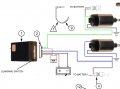
I have wired this door popper module.
I used relays with signals green and blue instead of wiring directly to solenoids. My question relates to the gray and yellow wires coming out of the module and shown connected to constant battery 12V.
The red wire is fused and it is connected to battery but makes no sense to me that yellow and gray are too. I have no instructions at all and this diagram is not really well developed.
Do you think it makes sense?
 

Attachments

geekoftheweek

Joined Oct 6, 2013
1,429
Why doesn't it make sense? There is nothing that says a module can't get power from more than one place. I'm going to assume the module is for a remote control door popper. With that assumption in mind I'm going to say the yellow is power for one side, gray for the other side, and red for the module power. It is probably a matter of the internal circuitry design works better with separate power for the various functions as opposed to a single power source.
 

geekoftheweek

Joined Oct 6, 2013
1,429
What's this door popper module, any other info or link?
It is used in automotive doors to open the door electrically. Some people use them to "shave" (remove and fill in the void) outer handles for a flat door surface. I would imagine it would come in handy for other reasons as well although it's generally just a cosmetic change rather than a functional change or improvement.

Just to answer a question that may or may not be asked you would run wires to some form of connector or something available externally to power the device in the event your battery discharges and is unable to operate the door.
 

crugorocks

Joined May 1, 2025
31
Test with a multimeter.Disconnect gray/yellow from 12V. With the module powered (red connected), press a button on the remote or trigger. Check if gray/yellow go high (12V) — if yes, they’re outputs. Or check if the module works normally without gray/yellow connected — if so, they may be optional triggers or override inputs.
 
It's not going to work as OP expects.
Car door lock solenoids/motors require both polarities of 12V power. It's reversed for open or close.
Typically two (external) high power relays are wired like an H-bridge to give this.
The modules themselves don't switch high current alone.

But we don't know the make/model of the module so we're stuck.
 

geekoftheweek

Joined Oct 6, 2013
1,429
I know what a door popper is just asking about for a link or model # for this particular module.
My apologies. To me this "What's this door popper module, any other info or link?" read as you did not understand what it was.

It's not going to work as OP expects.
Car door lock solenoids/motors require both polarities of 12V power. It's reversed for open or close.
Typically two (external) high power relays are wired like an H-bridge to give this.
The modules themselves don't switch high current alone.

But we don't know the make/model of the module so we're stuck.
It's not a mechanism to operate the locks. It is to operate the door latch. It only needs to go one direction.

Test with a multimeter.Disconnect gray/yellow from 12V. With the module powered (red connected), press a button on the remote or trigger. Check if gray/yellow go high (12V) — if yes, they’re outputs. Or check if the module works normally without gray/yellow connected — if so, they may be optional triggers or override inputs.
If they are meant to be outputs then why would the installation schematic be drawn to show them as power inputs?
 
Top