Help with dehumidifier PCB - NO POWER

Thread Starter

Mike Baker

Joined Aug 31, 2017
148
Hi All,

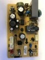
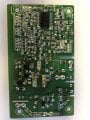
Im guessing there is a problem on the power circuit on this PCB as there is no power.

The fuse is ok.

The chip on the top P-IC1 is a ViPer 22A - How do i test this with a multi meter?

How do i test the relay with a multi meter?

Any other things to test?

Thanks
IMG_4042.JPG IMG_4044.JPG
 

Attachments

AlbertHall

Joined Jun 4, 2014
12,346
The fault with this type of circuit is very commonly that large grey rectangular capacitor at the top right of your photo of the top side of the board.
 

Lyonspride

Joined Jan 6, 2014
137
^^ Viper chips as a general thing, do run hot, but they do on occasion fail unexpectedly for no apparent reason.

Check all the external inputs, one will be an interlock of some sort, the others may be a temperature switch, a thermal fuse or similar devices that need to be "ok" for that to operate.

The 4 diodes on the back the PCB look like a crude a bridge rectifier, it's worth checking (very carefully) that your getting your mains x 1.7 (ish) out of that.
 

Thread Starter

Mike Baker

Joined Aug 31, 2017
148
^^ Viper chips as a general thing, do run hot, but they do on occasion fail unexpectedly for no apparent reason.

Check all the external inputs, one will be an interlock of some sort, the others may be a temperature switch, a thermal fuse or similar devices that need to be "ok" for that to operate.

The 4 diodes on the back the PCB look like a crude a bridge rectifier, it's worth checking (very carefully) that your getting your mains x 1.7 (ish) out of that.

Thanks for the reply,

I changed over the chip for a new one today and still its completely dead.

I am a bit nervous about testing 2 much with the multi meter when its got mains voltage in it..... lol
 

Lyonspride

Joined Jan 6, 2014
137
Thanks for the reply,

I changed over the chip for a new one today and still its completely dead.

I am a bit nervous about testing 2 much with the multi meter when its got mains voltage in it..... lol
Understandable, I do it every day so I guess i'm just used to it, it'd be nice to know whether it's getting power or not.

Rather than trying to reverse engineer the PCB I would test components, diodes are easy with a multimeter in diode test mode, 0.2-0.6 volts one way, zero the other, short circuit is more likely than open. Everything else on that PCB i'd expect to be visibly faulty, except the chip and the relay. Take the relay out to test it (so as not torisk damage anything by applying voltage to the PCB), you might get lucky and find high contact resistance, but relay contacts are tricky without a low resistance high current meter, personally I would replace that relay simply because it's a brand (Zong Chuan) that I have experience of being unreliable..... I actually just realised I have a pile of them on my bench in front of me as I type this.

If you want to test the PCB though, you need to emulate the inputs it would normally get, which means figuring out what is connected to it and what it should be doing.
When I did Delonghi DEM10 early last year I pulled the whole thing apart and then reconnected everything with all the covers and the PCB enclosure missing, the annoying part was having to find a way to keep the collection draw interlock switch closed (duct tape) I can't remember what was actually wrong with it though, I think in the end it was something stupid like a loose fuse holder or corroded connector.
 

Thread Starter

Mike Baker

Joined Aug 31, 2017
148
Understandable, I do it every day so I guess i'm just used to it, it'd be nice to know whether it's getting power or not.

Rather than trying to reverse engineer the PCB I would test components, diodes are easy with a multimeter in diode test mode, 0.2-0.6 volts one way, zero the other, short circuit is more likely than open. Everything else on that PCB i'd expect to be visibly faulty, except the chip and the relay. Take the relay out to test it (so as not torisk damage anything by applying voltage to the PCB), you might get lucky and find high contact resistance, but relay contacts are tricky without a low resistance high current meter, personally I would replace that relay simply because it's a brand (Zong Chuan) that I have experience of being unreliable..... I actually just realised I have a pile of them on my bench in front of me as I type this.


If you want to test the PCB though, you need to emulate the inputs it would normally get, which means figuring out what is connected to it and what it should be doing.
When I did Delonghi DEM10 early last year I pulled the whole thing apart and then reconnected everything with all the covers and the PCB enclosure missing, the annoying part was having to find a way to keep the collection draw interlock switch closed (duct tape) I can't remember what was actually wrong with it though, I think in the end it was something stupid like a loose fuse holder or corroded connector.
Thanks for your reply, so i have tested the diodes with my multi meter and have found some interesting results!

D2( DC M7) and D4 (DC ER1J) have readings in both directions, D1(DC M7) and D3(DC ER1J) do not.

So those diodes are shot..... Now where do i get some without spending a fortune on carridge or waiting weeks?IMG_4071.JPG
 

Lyonspride

Joined Jan 6, 2014
137
Might not be shot, there could be something connected across them, if the diode tester reads 0.00v in both directions then they're shot for certain, but otherwise lift a pin and measure again.

Also If you don't want to start prodding a live PCB with your meter, you could solder some wires to the PCB before powering up and then measure via croc clips, less chance of shaking, slipping, yelping and swearing.
 

Thread Starter

Mike Baker

Joined Aug 31, 2017
148
The 4 diodes on the back the PCB look like a crude a bridge rectifier, it's worth checking (very carefully) that your getting your mains x 1.7 (ish) out of that.[/QUOTE]

Sorry to sound like a complete noob but how would I go about this with a multi meter?

And you were correct that once lifted it was ok
 

Dodgydave

Joined Jun 22, 2012
11,302
To test diodes, set your dvm to Diode, and measure across it both ways, (the Cathode has the Black lead to it) it should read 0.7V and open circuit the other way round. Ideally lift one end of the diode from the pcb to get better results.
 

Thread Starter

Mike Baker

Joined Aug 31, 2017
148
Understandable, I do it every day so I guess i'm just used to it, it'd be nice to know whether it's getting power or not.

Rather than trying to reverse engineer the PCB I would test components, diodes are easy with a multimeter in diode test mode, 0.2-0.6 volts one way, zero the other, short circuit is more likely than open. Everything else on that PCB i'd expect to be visibly faulty, except the chip and the relay. Take the relay out to test it (so as not torisk damage anything by applying voltage to the PCB), you might get lucky and find high contact resistance, but relay contacts are tricky without a low resistance high current meter, personally I would replace that relay simply because it's a brand (Zong Chuan) that I have experience of being unreliable..... I actually just realised I have a pile of them on my bench in front of me as I type this.

If you want to test the PCB though, you need to emulate the inputs it would normally get, which means figuring out what is connected to it and what it should be doing.
When I did Delonghi DEM10 early last year I pulled the whole thing apart and then reconnected everything with all the covers and the PCB enclosure missing, the annoying part was having to find a way to keep the collection draw interlock switch closed (duct tape) I can't remember what was actually wrong with it though, I think in the end it was something stupid like a loose fuse holder or corroded connector.
Can you recommend a replacement relay for me please?
 

LesJones

Joined Jan 8, 2017
4,189
Have you tested to see if there is any mains input to the board ? Are there any interlock micro switches such as water collection container presesnt or full ?

Les.
 

Lyonspride

Joined Jan 6, 2014
137
Can you recommend a replacement relay for me please?
Datasheet here:
https://www.relayspec.com/specs/017775/835.pdf

Relays can always be a bit tricky to source, as there's no real standard for pin configurations.

Start with what you know, 8A 250VAC, 12V DC coil, and read datasheets. You could simply replace with the same relay, as they do appear to be easily available, but I would probably go looking to see what Omron or TE Schrack have to offer..... It's up to you :)

Perhaps http://uk.farnell.com/oeg-te-connec...000/relay-spst-no-250vac-30vdc-8a/dp/1891654#
 
Last edited:

Thread Starter

Mike Baker

Joined Aug 31, 2017
148
Datasheet here:
https://www.relayspec.com/specs/017775/835.pdf

Relays can always be a bit tricky to source, as there's no real standard for pin configurations.

Start with what you know, 8A 250VAC, 12V DC coil, and read datasheets. You could simply replace with the same relay, as they do appear to be easily available, but I would probably go looking to see what Omron or TE Schrack have to offer..... It's up to you :)

Perhaps http://uk.farnell.com/oeg-te-connec...000/relay-spst-no-250vac-30vdc-8a/dp/1891654#
Thanks for this lionspride, Unfortunately the relay seems to be fine.

The problem seems to be with the low power side of the circuit as we have good mains coming in.

Any ideas where and what to start testing? Thanks
 

dikhan

Joined Aug 27, 2010
1
Dear Mike
I have the same model and i found D7 diode was faulty , i removed the zener diode and power on dehumidifierScreenshot_20200419-172203_Samsung Internet.jpg and its working properly, but i dont know the voltage of this diode if i solder it on that place with new one, can u please help me to find out what value of faulty zener diode D7
 

LPtech

Joined Nov 4, 2020
1
Hello Mike Baker, Hi fellows !!!: "All roads lead to Rome!" 2020, Nov: i´m involved into a humidifier troubleshooting -same- the one you posted a couple years ago looking for help. I really don´t know if you finally were able to solve the stuff (God wanted it !) but, anyway here´s my personal experience fixing DeLonghi DEM 10 dehumidifier hoping it may help to all forum members. First, dehumidifier seemed dead (no power at all) so I dismounted all covers to test components. Before to try to repair the control board (guilty of the electrical failure in the end), i checked the following:
DEM 10 circuit.jpg

1- Power AC voltage to control board input (hot -also tested power cord!-), 2- Temperature sensor, humidity & water drawer interlocks & 3-compressor coils + overload protection & AC capacitor. Everything was ok so i went directly to the control board. Normally, some essential components must be checked first: i mean card fuse, AC input circuit items (varistor + R1, C1 & C2, & C + MOV before fuse) & i found a faulty 10 Ohms R1 open. After that, i tested IC1 ( SMPS controller IC VIP22A-check link: https://components101.com/ics/viper22a-smps-controller for further information), IC2 (voltage regulator), condensers E5, 6, 7 & 8, diodes D1-D4 looking for shortcircuits or failures & ...all was ok !!! _please, use control board picture at the beggining of the Post for components references_. Finally i changed R1 for a brand new one, put ev´rything together again & i gave life back to the "tareco"...Glad to be here & share with all of you...that´s all folks !
 

Nealjk

Joined Feb 7, 2021
4
Hello Mike Baker, Hi fellows !!!: "All roads lead to Rome!" 2020, Nov: i´m involved into a humidifier troubleshooting -same- the one you posted a couple years ago looking for help. I really don´t know if you finally were able to solve the stuff (God wanted it !) but, anyway here´s my personal experience fixing DeLonghi DEM 10 dehumidifier hoping it may help to all forum members. First, dehumidifier seemed dead (no power at all) so I dismounted all covers to test components. Before to try to repair the control board (guilty of the electrical failure in the end), i checked the following:
View attachment 221610

1- Power AC voltage to control board input (hot -also tested power cord!-), 2- Temperature sensor, humidity & water drawer interlocks & 3-compressor coils + overload protection & AC capacitor. Everything was ok so i went directly to the control board. Normally, some essential components must be checked first: i mean card fuse, AC input circuit items (varistor + R1, C1 & C2, & C + MOV before fuse) & i found a faulty 10 Ohms R1 open. After that, i tested IC1 ( SMPS controller IC VIP22A-check link: https://components101.com/ics/viper22a-smps-controller for further information), IC2 (voltage regulator), condensers E5, 6, 7 & 8, diodes D1-D4 looking for shortcircuits or failures & ...all was ok !!! _please, use control board picture at the beggining of the Post for components references_. Finally i changed R1 for a brand new one, put ev´rything together again & i gave life back to the "tareco"...Glad to be here & share with all of you...that´s all folks !
Hi,
I think I have the same problem as you with R1 being faulty, but it's so degraded I'm having trouble telling what colour the bands are. Any chance you remember what it was and could let me know what replacement I need?
 
Top