 Facebook
 Google
 GitHub
 Linkedin
Hello. I have a 1974 Seeburg Jukebox that I am building a wired remote control for. I have the schematics and can make it work using a Momentary DPDT toggle. I'd like to convert it to an arcade joystick using micro-switches so that it matches the theme in my garage with my arcade machines. Can anyone look at the schematics and tell me if this will work? I've second guessed myself enough now that I can't seem to do it. The only thing I know for certain is that if you volume up and down at the same it blows a fuse and can damage the amp.
Attachments
-
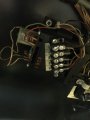 51.6 KB Views: 11
 -
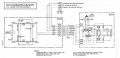 40.4 KB Views: 12


