Facebook
 Google
 GitHub
 Linkedin
Cde change, it seems to be some curls in to my brain for this change og code. Now changed pin output, to:
const int ledPin1 = 9; // Set pin's in use:
const int ledPin2 = 12;
const int ledPin3 = 13;
const int ledPin4 = 14;
however, I think the correct are like this:
const int pwm = 9 ; so and on. But it's different any way. What about "ledPin 1"-so and on?
const int ledPin1 = 9; // Set pin's in use:
const int ledPin2 = 12;
const int ledPin3 = 13;
const int ledPin4 = 14;
however, I think the correct are like this:
const int pwm = 9 ; so and on. But it's different any way. What about "ledPin 1"-so and on?
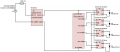
Arggh, thanks to be supervising! Links: http://schematics.com/project/23-flash-light-arduinoled-driver-10012016-1-25726/Thanks, Roof. OK, your schematic still doesn't have I- connected to GND, and that's a problem. I don't know where the current is going, but probably through the PWM pin for each driver. Eventually, your nano is going to fry, or maybe the driver module will fry. So please connect I- to GND.
Djsfantasi has already indicated how to use PWM in your Sketch to control on/off and brightness, if that's something you need to do. It can be useful to balance the red and green light pulses.