Facebook
 Google
 GitHub
 Linkedin

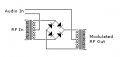
I wish you luck, Bill. May you find your dream job.The diode method works, but it is a kludge. It gets the point across well though.
Any AGC circuit (Automatic Gain Control) can be an AM modulator though. There are mixers that will suppress the two input carriers and come out with with just the sidebands that are pretty simple, not to mention chips (the 1496 comes to mind) to do the same thing.
When I get a chance I think I can explain it to your satisfaction. About to step out to go to a job fair, wish me luck.

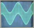
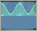
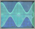
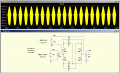
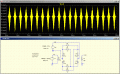
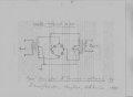
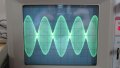
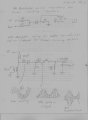
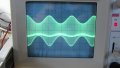
Funny you should bring up the LM1496; I just bought one on EBAY. I bought an LM1596, too. But I have already found a satisfactory solution to my need for a high fidelity AM modulator. Like I said in the post above, once I realized the concept it led to many ideas for how to create an AM modulator. I related how I used a simple two-resistor linear mixer in conjunction with your diode-resistor combination. I ran it through my IF amplifier but there was distortion. Assuming it was the resistors I switched to a linear mixer consisting of an audio transformer whose secondary was fed by a 100 uH inductor. I input the rf at the inductor and the af at the xformer and got a perfectly recreated sine, square, triangle, ramps and pulses. When I connected this to a tank to get the classic AM form there was just a little bit of distortion. I'll attach some pics.
As you can see, there's a bright band across the scope. I haven't demodulated it yet, but I'm guessing it will go away since it's part of the high frequency sine wave. When I turn the sweep so that I can look at it I notice it's the point where the hf sine turns to go back the other way but then a spike shoots past this turning point to "draw" the low frequency wave. I can put this band above ground or below ground depending on which way I turn the diode. I'll show a picture of this when I can post another pic. It only allowed two.
Attachments
-
 276.8 KB Views: 29
 -
 288.7 KB Views: 32
Last edited: