Help with AM modulator

Thread Starter

PRS

Joined Aug 24, 2008
989
The diode method works, but it is a kludge. It gets the point across well though.

Any AGC circuit (Automatic Gain Control) can be an AM modulator though. There are mixers that will suppress the two input carriers and come out with with just the sidebands that are pretty simple, not to mention chips (the 1496 comes to mind) to do the same thing.

When I get a chance I think I can explain it to your satisfaction. About to step out to go to a job fair, wish me luck.
I wish you luck, Bill. May you find your dream job. :rolleyes:

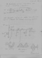
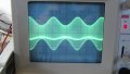
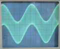
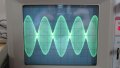
Funny you should bring up the LM1496; I just bought one on EBAY. I bought an LM1596, too. But I have already found a satisfactory solution to my need for a high fidelity AM modulator. Like I said in the post above, once I realized the concept it led to many ideas for how to create an AM modulator. I related how I used a simple two-resistor linear mixer in conjunction with your diode-resistor combination. I ran it through my IF amplifier but there was distortion. Assuming it was the resistors I switched to a linear mixer consisting of an audio transformer whose secondary was fed by a 100 uH inductor. I input the rf at the inductor and the af at the xformer and got a perfectly recreated sine, square, triangle, ramps and pulses. When I connected this to a tank to get the classic AM form there was just a little bit of distortion. I'll attach some pics.

As you can see, there's a bright band across the scope. I haven't demodulated it yet, but I'm guessing it will go away since it's part of the high frequency sine wave. When I turn the sweep so that I can look at it I notice it's the point where the hf sine turns to go back the other way but then a spike shoots past this turning point to "draw" the low frequency wave. I can put this band above ground or below ground depending on which way I turn the diode. I'll show a picture of this when I can post another pic. It only allowed two.
 

Attachments

Last edited:

Wendy

Joined Mar 24, 2008
23,797
It isn't so popular nowadays, but I specialized in communications (as in RF) in college. Most of it is obsolete, but useable for a lot of other stuff.

Still need me to go through the logic train?
 

t_n_k

Joined Mar 6, 2009
5,455
Perhaps the original circuit may have functioned more as anticipated if the output loading was appropriate. It looks like the effective low pass cut-off is too low and is allowing the modulation signal to appear in the output.
Also an even greater modulation signal amplitude would possibly increase the modulation index.
 

Thread Starter

PRS

Joined Aug 24, 2008
989
It isn't so popular nowadays, but I specialized in communications (as in RF) in college. Most of it is obsolete, but useable for a lot of other stuff.

Still need me to go through the logic train?
I'm still confused about how the diode turns the linearly mixed signal into the nonlinearly mixed signal. As I said, it seems to be a matter of 180 degrees in phase shift of one of the sidebands with respect to the other. Do you have an explanation in practical terms?
 

Thread Starter

PRS

Joined Aug 24, 2008
989
Perhaps the original circuit may have functioned more as anticipated if the output loading was appropriate. It looks like the effective low pass cut-off is too low and is allowing the modulation signal to appear in the output.
Also an even greater modulation signal amplitude would possibly increase the modulation index.

The first circuit didn't get its fair day in court. I put its output through my recently-made IF amplifier and I am only now discovering it to be a source of distortion. I'll have to fix it.

I'll play with the first circuit today after my chores and see what it can do. I think it should actually be a high fidelity circuit. Have you noticed that both circuits are purely passive? And, except for the LC tank at the output of the second one, they're not tuned. This is an advantage for me since I intend to put an AM modulator in its own aluminum box and use it for experiments. I'm waiting for a couple ICs in the mail so I can breadboard them and then pick the best modulator for the box.
 

Wendy

Joined Mar 24, 2008
23,797
OK, there are two completely different ways of looking at this, both work well.

1. A diode is the ultimate in non-linear devices. Besides the harmonics it will heterodyne signals, always, if it is rectifying a mix of signals. My personal bias is to use this side band generating approach for RF signals.

2. OK, take the basic signal that has both signals in it...


Note that this signal is floating around a DC reference, call it ground. The diode will chop off half this signal thusly...


Now this is predominantly an AC signal with a DC component. Remove the DC component (and filter the harmonics) you are left with a classic AM signal.


Something I would like to point out is that DC is the difference between the carrier and itself, in other words, it can be viewed as a heterodyned signal. So can the harmonics (the sum of the carrier with itself). Electronics usually has more than one way of viewing a circuit or process that is equally valid.

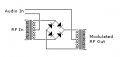
When I have some more time I would like to draw you a classic AM modulator that tends to suppress the RF carrier. It uses two HF transformers (usually toriods) and 4 diodes. Interested?
 

Attachments

Last edited:

alfacliff

Joined Dec 13, 2013
2,458
another way is to use the two transistors in series, the bottom one as the rf amp, and the top one to modulate the supply to the bottom one. adjust bias on top transistor so the bottom one has 1/2 supply voltage on it when no modulation applied, then the modulation will increase and decrease the output, thus am modulating the rf signal.
this cirxcuit has shown up in cb and ham radios in the last 10 years or so. also gives you a way to adjust the output power easily.
 

KL7AJ

Joined Nov 4, 2008
2,229

Thread Starter

PRS

Joined Aug 24, 2008
989
Thanks Bill. Actually I am a little embarrassed. You showed it to be ridiculously simple. I was overcomplicating it. And, yes, I would like to see the two-transformer, four diode approach. But aren't you just talking about an ordinary balanced mixer? Is that all an AM modulator is really doing? If so I have a really simple but effective mixer using a dual gate MOSFET which I used to combine the LO and the RF inputs to my radio's front end. Would this also work to modulate AM? Gotta try it.
 

Thread Starter

PRS

Joined Aug 24, 2008
989
another way is to use the two transistors in series, the bottom one as the rf amp, and the top one to modulate the supply to the bottom one. adjust bias on top transistor so the bottom one has 1/2 supply voltage on it when no modulation applied, then the modulation will increase and decrease the output, thus am modulating the rf signal.
this cirxcuit has shown up in cb and ham radios in the last 10 years or so. also gives you a way to adjust the output power easily.
Like a cascade amplifier? But with an input at each base? And when you say 1/2 Vcc, do you mean this to be at the emitter of the top BJT? Intuitively, couldn't you put the audio at the bottom and the rf at the top?
 

Thread Starter

PRS

Joined Aug 24, 2008
989
You need much greater carrier level...the bottom transistor needs to saturate.

Eric
I did notice in my recent foolings around that there had to be a certain amount of carrier amplitude before any modulation could be done. If you looked at the inductor/transformer modulator I posted I found out this morning that the rf decreased with increasing frequency. I divined that this was due to the XL of the inductor and by using a smaller inductor I could get a higher frequency. There seems to be a practical limit to this method of about 3 MHz. Or, at least, that's without using a lab amp to increase the signal so I can see it on my scope. I have an rf generator that has a maximum output voltage of 1 volt peak to peak and this got attenuated way too much by the circuit in question.
 

Wendy

Joined Mar 24, 2008
23,797
Thanks Bill. Actually I am a little embarrassed. You showed it to be ridiculously simple. I was overcomplicating it. And, yes, I would like to see the two-transformer, four diode approach. But aren't you just talking about an ordinary balanced mixer? Is that all an AM modulator is really doing? If so I have a really simple but effective mixer using a dual gate MOSFET which I used to combine the LO and the RF inputs to my radio's front end. Would this also work to modulate AM? Gotta try it.
Yes, I am talking about the classic balanced mixer. You have to have really matched diodes to suppress the RF carrier, so I have to wonder what would happen if you deliberately unbalance it.
 

KL7AJ

Joined Nov 4, 2008
2,229
Yes, I am talking about the classic balanced mixer. You have to have really matched diodes to suppress the RF carrier, so I have to wonder what would happen if you deliberately unbalance it.
Quite a few amateur radio transmitters use a doubly balanced mixer to create both SSB and AM signals (as well as CW). The method is to simply unbalance it using a small DC voltage on the IF port.

Eric
 

Thread Starter

PRS

Joined Aug 24, 2008
989
Yes, I am talking about the classic balanced mixer. You have to have really matched diodes to suppress the RF carrier, so I have to wonder what would happen if you deliberately unbalance it.
I built a balanced mixer back in the 90s and found it in a coffee can of old circuits this morning. I hooked it up using 1Mhz at the RF input and 1Khz at the LO input and watched the mix at the IF output. I was surprised to see what I call linear mixing. This is that combination of the RF top and bottom tracing the audio sine wave. I call this linear mixing because I can get the same effect just by inputting the same signals through 1K resistors whose other ends are combined. And resistors, as you know, are linear devices. In fact, the use of resistors outperformed the double balanced mixer up to 35 MHz (the limit of my scope).

So, in view of all of this, I'm beginning to wonder about those articles on modulators that insist the signal is nonlinearly mixed. The diode, a nonlinear device, just clips the linearly modulated wave and then an LC tank reconstructs the bottom as per the classic AM waveshape due to the energy in the tank bouncing back and forth between the inductor and the capacitor. The whole effect is to have shifted the bottom portion of the linearly mixed wave 180 degrees.

But there seems to be more than one way to get it done. I just looked at Alec's simulated balanced mixer and he has the correct output. I got the design I built from an old textbook and hooked it up like it showed in order to use it as a mixer in a super heterodyne receiver. Is Alec's way the standard hook up?
 
Last edited:

Thread Starter

PRS

Joined Aug 24, 2008
989
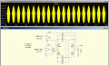
A sim of the post #34 circuit gives this. Any idea why the output is asymmetrical about zero volts?
I'll take a guess. The circuit is over-modulated and this made one or more harmonics increase or decrease in amplitude. See what happens when you back off the audio amplitude.
 
Last edited:

Alec_t

Joined Sep 17, 2013
15,130
Is Alec's way the standard hook up?
It's Bill's way, not mine :).
See what happens when you back off the audio amplitude.
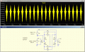
This is what happens; the asymmetry and distortion are greater. Since the circuit is symmetrical I don't see what introduces the asymmetry (unless it's just an artefact of the sim models).
 

Attachments

Wendy

Joined Mar 24, 2008
23,797
You are definitely overdriving that sucker, and as for it being my way the circuit is older than I am, and that is saying something.

Try reducing the audio, a lot. You need enough drive to overcome the diode drops, which will cause their own problems.

The linear mixer works, I would check wiring on any circuit that doesn't work twice.

Do not forget, it is a balanced mixer. The carrier is suppressed, as in not there. I never heard about adding DC to the audio input, I'm a bit curious about it.

You could always add the carrier back in a linear sort of way.
 

Thread Starter

PRS

Joined Aug 24, 2008
989
It's Bill's way, not mine :).
This is what happens; the asymmetry and distortion are greater. Since the circuit is symmetrical I don't see what introduces the asymmetry (unless it's just an artefact of the sim models).
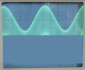
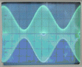
I made a mixer based on a textbook and the inputs and outputs are different from yours. I wondered if there was a way to hook up a mixer in different ways for different things so I hooked it up like yours. The best I could do is the oscilloscope image below. But the AF signal was a pure sine wave and that's not what you see there. I tweaked the amplitudes of both the AF and RF with worse results than what you see.

On the other hand when hooked up as per the schematic I got linear modulation. This could be used as per Bill's diode technique but why make this fancy circuit when you can just use two resistors to do the same thing?
 

Attachments

Top