Help with a hall effector timed LED change

Thread Starter

Cornbreadx

Joined Jan 2, 2026
18
Hey quick question on this. I decided to go ahead and make a chip to run this system. Can you double check that I have everything setup on the PCB correctly? CN1 is the incoming from the hall sensor. CN2 goes to the LEDs.View attachment 365143

Thanks in advance!!
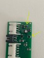
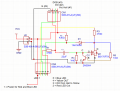
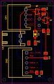
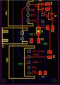
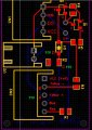
Oh... "C"1 to "C"2 ports are for the capacitor. I wanted that to have options to change the time between 30 s delay, 45, and 60 s delay.
 

Thread Starter

Cornbreadx

Joined Jan 2, 2026
18
Looks good.
Just make sure the values of the resistors are correct.
Ok, this is going to seem so crazy - but LED 1 and 2 both come on and stay on. I trip the hall effect sensor, and LED 2 stays on. LED 3 never comes on. This is with the chip design. I have traced this out at least 6 times, remade the schematic in EasyEDA, and I can't find anything wrong. I have even had the PCB manufacturer double check and they don't see anything wrong either. I can't figure why on the breadboard, everything works as intended, but with the chip... I get a crossed signal.
 

Attachments

sghioto

Joined Dec 31, 2017
8,634
Here is an updated PCB design with everything labeled. I can't figure why Blue and Red both come on and stay on until tripped by the hall effect - then red just stays on but never goes to yellow.
Only error I see is the Yellow LED is label backwards on the updated PCB
If RED stays on continuous it might be a short on the pcb around M1.
Do you have a meter for testing?
 
Last edited:

Thread Starter

Cornbreadx

Joined Jan 2, 2026
18
Read the voltage on the drain and gate of M1 if both blue and red LEDs are on at the same time.
Hold up on this. For some reason, it started working - kind of. Don't ask me why - I have no idea. Here is the long and short of it.

First image:
I got voltage reads from the breadboard and yup... voltage was slowly going up until the light changed from Red to Yellow. Ended at 3.2v

Then I checked voltage reads from the chip (Second Image)

Started going up as expected, and then it jumped to 11v at the end. No yellow light. Blue and Red were not on at the same time (for no explained reason what-so-ever) this time - just Blue when the hall effect was one way, and when tripped, just red the other way.

Now... however... nothing is working suddenly. I just powered it up again to do some further checks and now no lights come on with the chip version.

I think I am beyond frustrated and can't look at it anymore given that I have spent 2 days checking and re-checking everything to have more questions than answers. Not your fault - just annoying.
 

Attachments

Thread Starter

Cornbreadx

Joined Jan 2, 2026
18
Take a break and will figure this out when your up to it again. :)
Thanks so much for your patience. I believe I found the problem. On the chip, there are two resistors that have the wrong rating. On LCSC, the part number imported to EasyEDA Pro was listed as follows:


1mΩ 500mW ±1% ±150ppm/℃ 0805 Chip Resistor - Surface Mount RoHS

They should have been 1M instead of 1m. :(

I removed the two resistors that are marked with yellow arrows. I then retrofitted connectors to them to attach to my breadboard and then put the correct resistors there. Wouldn't you know it - everything started working again.

I am going to have the company remake these. What a stupid mistake that I didn't catch. Very frustrating to have to buy them again. Oh well... such is life. I might just order a roll of 1M surface mount resistors and change all of these out.

Thanks again for all your help - you are a wizard in my mind! haha.
 

Attachments

Top