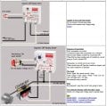
help with a circuit design

Thread Starter

corvairbob

Joined Mar 31, 2023
27
i have a circuit i want to wire up. this sircuit will be 120vac what it will do is i press a button and it powers a device for lets say 10 seconds and turns off. it then sets there until that button is again pressed. i now have 2 relays. a timer relay and standard relay.

this is the relay numbers i now havekrpat1ag 8 pin socket mount
also a 319 time delay relay

also i have a handle on a
Dayton 6A857 Solid State Timer Off Delay SPST-NO 24-240VAC 1A Industrial Control

so this relay may work and would be a lot easier to connect to that compressor.
 
Last edited by a moderator:

ericgibbs

Joined Jan 29, 2010
21,511
hi cb,
You state you want to operate from 120Vac , using the Dayton 6A857 at 120Vac

What current rating is the relay contacts load?
E

clip:
The Dayton 6A857 is an encapsulated single-function off-delay solid-state timer relay featuring an adjustable 0.5 to 10-second timing range, a 24-240VAC input voltage, and a 1A SPST-NO switch rating. [1, 2]


Technical Specifications
    • Function: Off-delay (delay starts after control voltage/power is removed or switched)
    • Timing Range: 0.5 to 10 seconds (adjustable via potentiometer)
    • Input / Control Voltage: 24 to 240VAC (50/60 Hz)
    • Contact Form: SPST-NO (Single-Pole, Single-Throw, Normally Open)
    • Contact Current Rating: 1A resistive at 24 to 240VAC
    • Output Type: Solid-state
    • Mounting / Connections: Surface mount with 5 pins / quick-connect or screw terminals
    • Sealing: Fully encapsulated/sealed against dust and moisture [1, 2, 3, 4, 5, 6, 7]
 
That relay is rated to handle 1 amp. That's 120W. Is that good enough? That's 1 amp resistive load, not a motor or transformer load. What are you using it on? Also you say:
it powers a device for lets say 10 seconds and turns off.
What is the "device"? Is 10 seconds the longest time you want? If you want longer then that relay won't fit the bill.
 
i now have 2 relays. a timer relay and standard relay.
Do you plan on using the standard relay to control a much larger load?
The devil is in the details. We can help you but you have to help us help you. Otherwise we might have you building a space shuttle.

Also, if you start with a schematic (electrical diagram) we can help there too. We just don't like to provide engineering services for free.
 

MisterBill2

Joined Jan 23, 2018
27,883
Actually, much of this site IS providing " engineering services for free." but mostly when the answers are not a big deal amount of effort. That is a big part of why I am here, and certainly why many others are here. Sometimes we decline to provide huge projects for free, though.
 

B-JoJo-S

Joined Jan 3, 2026
450
Actually, much of this site IS providing " engineering services for free."
While small projects like 'how to hook up an LED' or other minor projects can be something we're happy to help with - it usually starts with the thread starter (TS) having their own starting point. It looks like the TS has an idea but wants a diagram as to how to hook it up. But we don't know several factors. 'What the TS wants to control' is a big issue. Controlling a resistive load has different considerations than controlling an inductive load. For us to simply provide a diagram could lead to issues and even possible property damage if not done right. We're not messing with coin cells, we're talking 120VAC.
 

B-JoJo-S

Joined Jan 3, 2026
450
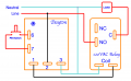
Best I got from your description. Keep in mind I don't know your load or the specs of the standard relay.
EDIT: Drawing removed for inaccuracy. See post #13 END EDIT
About your "Standard Relay" - it must be rated for 120VAC CONTINUOUS DUTY otherwise it will burn up. The relay contacts should be rated to handle 120VAC at an amperage that is equal or twice the anticipated current draw by the load. IF your contacts are rated for 10 amps and you plan on running something that draws 1/4 amp then the contacts will likely develop scale and render the relay useless. The relay needs to be sized correctly for the load.
 
Last edited:

B-JoJo-S

Joined Jan 3, 2026
450
Now; I've assumed your standard relay has both NC (Normally Closed) and NO (Normally Open) contacts. I've chosen to connect line power to the NO. That way when the system is not energized there's not an open connection holding line power. You could connect line power to the C and use the NO to run your load. But then whenever your system is not energized there is power on the NC. A potential shock or short hazard. (The C contact is just the Common contact)
 

MisterBill2

Joined Jan 23, 2018
27,883
Certainly, some of us who made no contributions did not have access to the Data for Dayton 6A857 device, which is very suitable for this application. Fortunately "B-JOJO" did!
 

B-JoJo-S

Joined Jan 3, 2026
450
MisterBill2 Fortunately ericgibbs had the info in post #12. I was late coming to the proper conclusion about the wiring. If not for Eric Gibbs my original drawing would have been incorrect. That's why I deleted the drawing from post #8. It was incorrect.

As for the size of the load and the capacity of the standard relay - that - we haven't heard yet. We don't know what or how big the load is going to be. Post #12 has the best info on the setup.
 
Top