You might want some sort of damping on the circuit. For example, must connect in the empty position for a few seconds before it is "Empty". You don't want some bouncing on a rough field to trigger the empty signal. If you are ok with no reset of the alarm, (or a simple toggle switch that you must REMEMBER to reset before you go out in the field, then the circuit becomes really easy. A Green LED to indicate FULL would help you remember to turn on the toggle switch each tank full.
Triggered for low level fluid with alarm deactivated
Triggered for low fluid level - alarm active
Full fluid level
You might want some sort of damping on the circuit. For example, must connect in the empty position for a few seconds before it is "Empty". You don't want some bouncing on a rough field to trigger the empty signal. If you are ok with no reset of the alarm, (or a simple toggle switch that you must REMEMBER to reset before you go out in the field, then the circuit becomes really easy. A Green LED to indicate FULL would help you remember to turn on the toggle switch each tank full.
You might want some sort of damping on the circuit. For example, must connect in the empty position for a few seconds before it is "Empty". You don't want some bouncing on a rough field to trigger the empty signal. If you are ok with no reset of the alarm, (or a simple toggle switch that you must REMEMBER to reset before you go out in the field, then the circuit becomes really easy. A Green LED to indicate FULL would help you remember to turn on the toggle switch each tank full.
OK - this is where I have got to today. I know it is not ideal but I can't work this out (this is just a pseudo diagram)
My thoughts are....
Circuit is energised with ignition of tractor
Float triggers a latch circuit (555) which sends pin 3 HIGH
Pin 3 is connected to the 'common' pin on a mechanical relay
The relay NC pin is connected to another 555 in astable mode which sounds the piezo and flashes LED
To silence the alarm one would press a momentary switch connected to a third 555 in a latch configuration to then energise the relay disconnecting the NC pin and silencing the astable 555
This would then allow me to silence with a momentary switch, reset to whole circuit when the tractor ignition is turned off (although it will sound again if the float triggers the latch circuit).
I don't want a mechanical relay, but the only components I have here are a handful of 555 timers, some PN2222A transistors, some NPN MOSFETS and some relays.
Is there a better way to be doing this or should I just revert to my Arduino based circuit which in reality is far simpler for me to program the logic. I have decided to have a go at using discrete components as an educational exercise.
And in case a picture of the tractor helps peoples imaginations
Connect your pin 2 and 5 to the "common" of your float switch.
Connect 1 terminal of your float switch to + Vcc (thru a resistor of , say, 10K) and the other to Ground, again thru 10 K.
This will act as an Astable, the time period dependent on the Float Switch changeovers.
Connect your pin 2 and 5 to the "common" of your float switch.
Connect 1 terminal of your float switch to + Vcc (thru a resistor of , say, 10K) and the other to Ground, again thru 10 K.
This will act as an Astable, the time period dependent on the Float Switch changeovers.
Sorry for the confusion, the switch highlighted in blue is your float switch. Everything else is simple LED and 12v source outside of your tank. Of the wires exiting your float switch, the black would be on bottom of the Highlighted block, brown wire would be top right and blue wire would be top left.
COM-L1 is connected when the tank is Full
COM-L2 is connected when the tank is Empty
Connect Pins 2 and 6 of the 555 to the COM point.
Connect L1 to +V
Connect L2 to GND
When the tank is Full, Pin 3 of the 555 goes LOW and remains so till ..... this condition
When the tank is Empty, Pin 3 of the 555 goes HIGH and remains so till ..... this condition
If Pin 3 has to do the Opposite, interchange L1 and L2 connections.
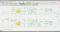
Here is an implementation of the state transition diagram I showed in post #10, using only two 555s. If you used a Son-alert, you could eliminate the second 555.
For the simulation, I collapse the time scale so that things that would take minutes in real time take only 1400ms. The test sequence is as follows:
Ignition is turned on at 0.1s, off at 1s, back on at 1.1s. See V(sw12V).
Tank runs out of water at 0.6s; never refilled. See V(float).
Silence button is pushed for 20ms at 0.8s and 1.2s. See V(silence).
Note that the switches utilized in the simulation are closed whenever their control voltage is >0V. That is just how LTSpice models switches. Think of V(float) and V(silence) as external influences; they are not real signals in the circuit.
The first 555 is used as the Latch. It comes up triggered when power is first applied due to R1 C1. Closing S1 clears the Latch. See V(enable).
The second 555 is used only to make the tone. Note that it can oscillate only when V(enable) is high. See V(tone).
The test sequence shows the tank running dry, tone begins, operator silences it. Tractor is parked, and restarted without refilling the tank. Alarm sounds to alert the operator that he forgot to refill the tank. He silences it to drive over to the filling station...
As best I understand them, this circuit meets all of the operating requirements with a single, commonly available chip. Note that no 1% resistors are required; just about anything will work. See post #12 for operation.
The Float contact is fed thru an analog switch that is open on power up and closed after a short time delay (I've shown form A contacts on the schematic but they would actually be the corresponding Float contact). This provides time for the circuit to initialize. After power up, the contacts are connected to the triggers of the 556 timers. The contact that is closed will cause the corresponding 556 to generate a pulse. If the Empty contact is closed, its output relay will latch and light its LED. This relay can be reset by pressing the ALM off button. If the "Full" contact is closed, it resets the "Empty" relay if it were previously latched. Any subsequent contact state changes will retrigger the corresponding timer. The output relays can be changed to MOSFETS, but I didn't want to spend the time unless the OP is interested.
Here is an implementation of the state transition diagram I showed in post #10, using only two 555s. If you used a Son-alert, you could eliminate the second 555.
For the simulation, I collapse the time scale so that things that would take minutes in real time take only 1400ms. The test sequence is as follows:
Ignition is turned on at 0.1s, off at 1s, back on at 1.1s. See V(sw12V).
Tank runs out of water at 0.6s; never refilled. See V(float).
Silence button is pushed for 20ms at 0.8s and 1.2s. See V(silence).
Note that the switches utilized in the simulation are closed whenever their control voltage is >0V. That is just how LTSpice models switches. Think of V(float) and V(silence) as external influences; they are not real signals in the circuit.
The first 555 is used as the Latch. It comes up triggered when power is first applied due to R1 C1. Closing S1 clears the Latch. See V(enable).
The second 555 is used only to make the tone. Note that it can oscillate only when V(enable) is high. See V(tone).
The test sequence shows the tank running dry, tone begins, operator silences it. Tractor is parked, and restarted without refilling the tank. Alarm sounds to alert the operator that he forgot to refill the tank. He silences it to drive over to the filling station...
@MikeML - it seems to be working but I am using a self driven piezo and I think I need to do something different with C3 / Rs. If I take C3 and Rs out of the circuit the piezo sounds as soon as the circuit is powered regardless of the float switch state (SW S2). If I put C3 / Rs back in the circuit works as expected but the piezo sound is very low and continuous. I would like the piezo to pulse on and off if possible. I assume that means that U2 should be in Astable mode with an appropriate RC design to allow the OUT pin to pulse HIGH/LOW ?
If using a 12V Sone-alert (self-oscillating piezo sounder) that has two leads, connect the red lead to what is now the junction of S2 and R3; connect the black lead to ground. Ditch R3 and everything to the right of R3.
 Facebook
 Google
 GitHub
 Linkedin