Facebook
 Google
 GitHub
 Linkedin
dosgringos
- Joined Nov 10, 2015
- 7
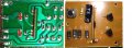
You want to remove the two triacs and solder the two pads linked in yellow.Hey all,
I'm curious if anyone was able to find a soldering solution the OP was asking about for their board as I have the same one (It looks like dosgringos has a slightly different controller).
I want to bypass the 8 functions and keep the lights on all the time.
I'll post pictures for reference:
View attachment 96199 View attachment 96198
Thanks in advance.
Attachments
-
 172.8 KB Views: 384