Facebook
 Google
 GitHub
 Linkedin
Hi all! I'm Luca and i'm from Italy. I'm not expert in electronics but in my spare time i like to create and study (in the limit of my ability) simply electronic projects useful for everyday life.
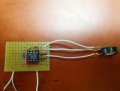
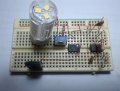
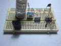
Some days ago i was asked from a friend to make a simply circuit to dimmer a led string. I discovered that the simplest way to do it is by using a 555 as PWM generator and a MOSFET. In order to go step by step i decided to start realizing a simple single led dimming circuit (to which i could add a mosfet afterwards). I already got a SA555 timer at home and so.. i started prototyping it on a stripboard.
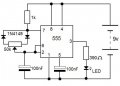
Actually the result is that i always got an High output on pin 3, and even rotating the 50k trimmer i cannot modulate led brightness (the led is always ON).
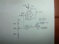
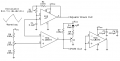
I attached the schematic i'm using.. I would be pleased if somebody could tell me if the scheme is valid or not.
In the meanwhile i'm trying to get more 555 timers to test (maybe the one i got was broken).
Thanks in advance.
Some days ago i was asked from a friend to make a simply circuit to dimmer a led string. I discovered that the simplest way to do it is by using a 555 as PWM generator and a MOSFET. In order to go step by step i decided to start realizing a simple single led dimming circuit (to which i could add a mosfet afterwards). I already got a SA555 timer at home and so.. i started prototyping it on a stripboard.
Actually the result is that i always got an High output on pin 3, and even rotating the 50k trimmer i cannot modulate led brightness (the led is always ON).
I attached the schematic i'm using.. I would be pleased if somebody could tell me if the scheme is valid or not.
In the meanwhile i'm trying to get more 555 timers to test (maybe the one i got was broken).
Thanks in advance.
Attachments
-
 45.4 KB Views: 71