
 Facebook
 Google
 GitHub
 Linkedin
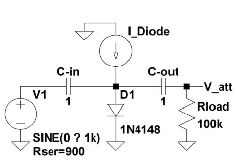
Hello, for a lab we recently constructed a voltage divider that used diodes. We had to obtain a 10:1 ratio using the circuit featured below.
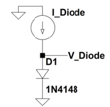
In order to find I_Diode, we had to simulate the circuit below. We had to match the slope up to the resistor value we calculated for the voltage output ratio. We then took the current value at the slope.
Anyway, I'm just wondering how the first circuit works, the voltage attenuator circuit. How does that circuit act as a voltage divider?
Thank you for any possible help. I greatly appreciate it.
In order to find I_Diode, we had to simulate the circuit below. We had to match the slope up to the resistor value we calculated for the voltage output ratio. We then took the current value at the slope.
Anyway, I'm just wondering how the first circuit works, the voltage attenuator circuit. How does that circuit act as a voltage divider?
Thank you for any possible help. I greatly appreciate it.






