When you ask for help on a problem like this, it's important that your work be easy to read. For example, your symbol R3 looks like β3, and the last line has such small letters and numerals I can't make out a lot of it. If I have to devote more effort to reading your handwriting than solving the problem, I'm not inclined to spend the time. Please repost something easy to read. It would be best to type the result than provide a handwritten text.
This is my try for section a, i got i3 by matrix calculator . i tried to do the same for finding Rth and Vth at section b but i got somthing strange . View attachment 250564
I have to agree with post #4 this is a little too hard to read. It makes it too hard to help someone when the text type is too hard to read.
Try writing the characters very clearly or just type them out.
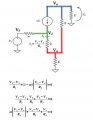
You also might want to note this looks like a transistor circuit with the transistor modeled as a linear current controlled current source.
I took another quick look and it looks like you may not have enough terms in the numerator of your result.
What you could do to check this is:
1. Choose some resistor values, like R1=1, R2=2, R3=3, etc.
2. Calculate the current through all resistors, iR1, iR2, iR3, etc.
3. Use "the sum of all currents into a node equals zero" to check your result.
Check out Kirchhoff's Current Law.
Once you calculate the currents through all resistors the sum for every node must work out to zero or there is a mistake in the notwork calculation. This is a standard way to check.
You can also do this symbolically but it's a little harder to do.
If you find that it works, then change the resistor values to some values not linearly related to the other set. For example, if you chose R1=1 and R2=2 the first time, then dont choose R1=2 and R2=4 the next time, but choose something like R1=2 and R2=5. This ensures you dont create the same circuit just scaled. Ideally you should use prime numbers for the values then another set of prime numbers for the second set. So maybe 1,3,5,7,11 and then 3,5,7,11,13 or even mix them up 5,3,11,7,13 something like that. In each case the sum into every node must come out to zero or there is a mistake somewhere.
The circuit is susceptible to nodal analysis with three node equations as shown. But solving the equations for Vo as a function of Vs isn't practical without math software such as Maple. Not sure what would be the easiest way to find the resistance seen by RL. (open-circuit voltage / short-circuit current)?
 Facebook
 Google
 GitHub
 Linkedin