HELP to identify a power supply

Thread Starter

captoro

Joined Jun 21, 2009
207
hello,

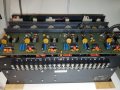
I have uploaded some picture of the device I recently put my hands on.
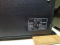
Its a power supply from the 80's I guess. I was told it was destined to GM.
The I found a paper with a from and to address. It was going to Chrysler corporation in Alabama!
That box was seal when I received it. Weighs a ton because of the huge transformers inside.
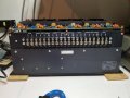
I plugged it in and I cant seem to get some voltage out, Where the heck is the ground ? what are those SEN and RET pins ?
Any help would be appreciated. maybe a manual ?

Ken
 

Attachments

Last edited:

dendad

Joined Feb 20, 2016
4,451
The sense and return pins are for wires that come from the load power connections so the voltage at the load is sensed, the drop in the cables in therefore countered bu the power supply volts increasing to cancel that out.
 

sagor

Joined Mar 10, 2019
903
It seems to be a multi-voltage supply, with a -5V, +5V, +12V , +15V and a +24V. The OUT and RET are the main voltage outputs, the SEN and SEN RET are for remote sensing of the voltage. Remote sensing is used to compensate for voltage drop over longer runs of wiring.
It also has negative voltages out, though I suspect they are low current (1A or less) due to the fact there is no remote sensing for those outputs.
If there are no output voltages on the OUT and RET, it could be that the SEN is not detecting any voltage at all, and shutting down. Usually (in most cases), it is safe to connect SEN to OUT, and SEN RET to RET. All that does is sense the voltage at the terminal strip. However, that unit may behave differently, do so at your own risk... (use a small value resistor to connect them, like 100 ohm)
It is hard to say what the current capacity is. Based on the transistors visible (6 of them in total), I would guess they are for the "major" outputs, being the +5, +12 and +15V. Two pass transistors for each voltage would probably limit to around 10A or so. If there are more transistors hidden from view, the current capacity may be more.
The +24V may be an unregulated output, maybe a direct transformer rectified output.

EDIT: On second thought, not sure if those are -ve voltages or separate out/sense terminals. The symbols are hard to make out on the circuit board...
 
Last edited:

MisterBill2

Joined Jan 23, 2018
18,167
Before applying any line power it is important to have the sense terminals connectedto the output that they should be sensing. Some brands and models of power supply are damaged almost instantly if they are powered up without the sense lines connected. This is one possibility.
In addition, there may be current limit adjustments that may be set to zero, which will prevent any output voltage. And there may well be an output over voltage limit adjustment that must be set.
So now you have a bunch of things to check.
 

Thread Starter

captoro

Joined Jun 21, 2009
207
The sense and return pins are for wires that come from the load power connections so the voltage at the load is sensed, the drop in the cables in therefore countered bu the power supply volts increasing to cancel that out.
connected SEN to OUT, and SEN RET to RET and I can read voltage now.
thank you

Ken
 

MisterBill2

Joined Jan 23, 2018
18,167
The pictures do show that the regulator IC devices are an older style that is not presently available. And with no current rating shown it will be a challenge to know the capabilities of the outputs. Fortunately the output connections are grouped, and certainly each output is isolated from the others. So to measure the voltages you will need to read across each set of connections.
You have not shown the input power connections and so there is no way that we can comment about them being correct or not. Many supplies have dual voltage inputs and must have at least one jumper installed to function at all. So we still need a picture of the other side.
 

AnalogKid

Joined Aug 1, 2013
10,986
The three big outputs also have current sensing for overcurrent protection. Please post a top-down closeup photo of one of the larger retulator circuits. Particularly, the text on top of the round metal can and the small power transistor (or whatever).

ak
 

AlbertHall

Joined Jun 4, 2014
12,345
There are six regulator panels and seven outputs so, as has been said, maybe the 24V is unregulated.
Each regulator panel has two adjusters - presumably one for output voltage and one for current limit.
 

MisterBill2

Joined Jan 23, 2018
18,167
I see six regulator sections and seven outputs, and so I am guessing that one output is not regulated. That one should be active if the power input connection is correct. Since the voltage spec states both 115 and 230 volts, there MUST be something more than a simple connection to power this supply.
Show us the AC input connections area since that is probably where the no-output problem is located.
 

AlbertHall

Joined Jun 4, 2014
12,345
I see six regulator sections and seven outputs, and so I am guessing that one output is not regulated. That one should be active if the power input connection is correct. Since the voltage spec states both 115 and 230 volts, there MUST be something more than a simple connection to power this supply.
Show us the AC input connections area since that is probably where the no-output problem is located.
Read post #5
 

MisterBill2

Joined Jan 23, 2018
18,167
Read post #5
Post #5 bears no relationship to the AC power input connections. It ONLY addresses the sense terminal connections.

Please understand that power supplies have some separation between the AC power input connections and the DC power output connections, and note that I am asking for additional information. Also, it is important to not connect the AC mains voltage to any of the output terminals.
 

AlbertHall

Joined Jun 4, 2014
12,345
Post #5 bears no relationship to the AC power input connections. It ONLY addresses the sense terminal connections.

Please understand that power supplies have some separation between the AC power input connections and the DC power output connections, and note that I am asking for additional information. Also, it is important to not connect the AC mains voltage to any of the output terminals.
Post #5 says the supply is now working after linking the sense terminals.
 

Thread Starter

captoro

Joined Jun 21, 2009
207
I have all the voltage on the output, But When I put on a load I hear a click anmd and there is no more voltage. OI need to shut down the device and turn on so voltage goes back up. BY a load I just applied voltage to an IC to power it. few mA , not much current. Using 5v and -5 v only. I get the voltage good on a voltmeter. You can view the picture for set up.

Ken
 

Attachments

AnalogKid

Joined Aug 1, 2013
10,986
Sense connections should be zero ohms. If you are driving a heavy, remote load, the main output and its return connect with heavy gauge wire (#10, #0, whatever) and the sense and sense return are a #22 twisted pair connected directly to the main outputs *at the load*. To disable remote sensing, short the sense inputs to the main outputs at the supply.

ak
 
Top