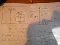
It works! I only had to substitute the shitty lm741 with a lm358
Now I have an amplified voltage related to the gain equation. Great
Now I only need to build a comparator in such a way that when the voltage (that reflect the temperature) surpasses a certain value, I get a positive value and the relay activates.
You can use two op amp gates to create a window comparator, you can build it using a single gate with hysteresis,,,
i would use a Lm324 chip, it has 4 gates.
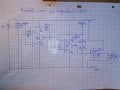
The voltage that leaves the first opamp enters the 2 (comparator) and compares the voltage with 4.28v which is the voltage divider's fixed value (add a pot?), once it is higher that the reference's value, positive voltage will leave the lm311 and enter the relay, which will activate the fan
A few problems with that circuit.
1) If the opamp is intended as a gain stage its inverting input should be taken from the junction of the two resistors. The other end of the 2.2k resistor should go to ground.
2) The 311 has an open-collector output so can only sink current (i.e pull low).
3) The relay needs a reverse-biased spike-suppression diode connected across its coil.
4) The 311 may not be able to sink enough current to drive the relay properly (depending on the relay spec).
5) The circuit does not provide hysteresis.
I've tested the relay plugging it directly to a 9v battery and it triggers.
That's good enough for me.
All I'm interested is that under my conditions, a voltage gets out from the comparator
It works! I only had to substitute the shitty lm741 with a lm358
Now I have an amplified voltage related to the gain equation. Great
Now I only need to build a comparator in such a way that when the voltage (that reflect the temperature) surpasses a certain value, I get a positive value and the relay activates.
I don't understand why you need to amplify the LM35 output to feed the comparator. If it's just to include an op-amp into the project, that's a good enough reason. But you can make a very fine thermostat without the amplification step. Same comment about the window comparator - you don't need a window, you just need on/off with (a small, adjustable) hysteresis, right? Maybe I've misunderstood the goals. I try to simplify things in design but maybe you're trying to complicate them on purpose?
Yes, I just need a on/off hysteresis of circa 1v (should be over 10° of trigger).
I realize that I've overcomplicated the first part... but I've learned a lot in these days, so it was useful.
I just need a way to make the second part (comparator) work. I'm studying how the hysteresis wok, as I actually do no know how to add the two thresholds.
That italian project I posted (post #16) suggests the use of a bjt.
A MOSFET is a better choice than a BJT here, because you need only two states, on or off. The MOSFET is ideal for that chore. A BJT can work, but requires current to hold it "on". An advantage of the BJT is that it needs less than a volt on the base to turn it on, versus 10V on the gate of a MOSFET. But I think this is not a problem in your circuit.
If you had read post #2 you would have seen that other members agree with me. 741 cannot read low voltages. <1v is a low voltage.
My circuit works. I just need to add hysteresis so I can remove noise.
 Facebook
 Google
 GitHub
 Linkedin