Nope, I'm preparing for an exam, and have no study material but the previous exam papers. and I'm stuck at some problems because my major isn't power electronics, I hope I can find some help here!, thanks
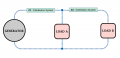
It's been a very long time since I ever looked at a power problem. Can anyone explain what Z1 & Z2 are meant to represent? Why is one a 3-terminal device and the other a 2-terminal device?
It's been a very long time since I ever looked at a power problem. Can anyone explain what Z1 & Z2 are meant to represent? Why is one a 3-terminal device and the other a 2-terminal device?
Z1 and Z2 both represent a complex impedance expressed in Cartesian form. The lower case j is the imaginary unit. Z1 has a single input and the output is connected to Z2 and Load A (they are the same point). Z2 has a single input from Z1 and an output that goes to Load B. A compex impedance has a real part which is equivalent to a frequency independent resistance, and an imaginary part which represents a frequency dependent reactance. The sign of the reactance describes either an inductor (positive) or a capacitor (negative).
Convenience. A complex impedance, as shown in the diagram, is a two terminal, lossy inductive network. Furthermore Z1 and Z2 have identical impedance characteristics. There is no other way to interpret the drawing. There is no such thing as a passive impedance with one input and two outputs at low frequencies. I don't know about common practice for power circuits, but I sure cannot imagine the behavior of a passive network with one input and two outputs at power line frequencies.
At very high frequencies, the Wilkinson Power Divider is a passive circuit with one input and two outputs:
... Still trying to solve this.
Is it possible or correct to assume that the voltage at Load A is the same as the voltage between
\(Z_1\) and \(Z_2\) ?
Z1 and Z2 both represent a complex impedance expressed in Cartesian form. The lower case j is the imaginary unit. Z1 has a single input and the output is connected to Z2 and Load A (they are the same point). Z2 has a single input from Z1 and an output that goes to Load B. A compex impedance has a real part which is equivalent to a frequency independent resistance, and an imaginary part which represents a frequency dependent reactance. The sign of the reactance describes either an inductor (positive) or a capacitor (negative).
I think you can arrive at a solution by making this assumption. If anybody can provide a justification for doing it another way, then that solution should be evaluated as well to see if they agree or disagree.
In order to do this you need to insert something between Load A and Z2. Pray tell, what might that be given the lack of information in the original diagram
In keeping with the notion that Z1 & Z2 are parts of an electrical distribution system, equivalent to equal lengths of heavy gauge electrical cable, the distribution for Load B would originate at the drop for Load A. Just my opinion from a very flawed diagram.
Do you happen to have a better drawing?
I ask because a complex impedance circuit element does not have three terminals it would have just two terminals. If you dont, then you probably have to assume the circuit looks like it does in the post just before this one.
That said, if you really want to understand the concepts behind this kind of thing then you really should look up at least what these are:
1. Real power
2. Apparent power
3. Reactive power
That should help you start to understand these kinds of circuits.
Thanks for your reply, I do understand these concepts, I solved the problem using the diagram showed above but I need to double check the answers, I would appreciate if someone posts the final answers to this problem. thank you!
In keeping with the notion that Z1 & Z2 are parts of an electrical distribution system, equivalent to equal lengths of heavy gauge electrical cable, the distribution for Load B would originate at the drop for Load A. Just my opinion from a very flawed diagram.
thank you so much for this clarification, made it clear to me and it definitely makes more sense. I solved the problem but I need to double check the final answers, if you tried to solve it and got to some final answers could you please share them so I can double check?, thank you!
Thanks for your reply, I do understand these concepts, I solved the problem using the diagram showed above but I need to double check the answers, I would appreciate if someone posts the final answers to this problem. thank you!
Hi ma88,
... It seems to me that the voltage, Va, between the Z1 and Z2 components should just be a magnitude, without any angular specification, in a manner that would be read by taking a voltmeter reading at that location. This would conform with the initial problem request of determining a 'terminal voltage'.
... The magnitude value shown in the post above for Va is approximately correct, as far as I can tell.
If there are any additional instructive comments ... please inform us.
 Facebook
 Google
 GitHub
 Linkedin

")