Help required in UK with project

ericgibbs

Joined Jan 29, 2010
21,442
hi,
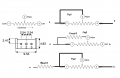
The DS2E High sensitivity has a 720 ohm coil.

Because the 8 amp relay has has approx half the resistance of the high sensitivity DS2E means that the current requirement of the 8A relay is double.

That will be 12v/360 =33mA, which a general purpose transistor could easily drive.

E
 

Attachments

Thread Starter

Nick Bacon

Joined Nov 7, 2016
130
Thanks for your help on this.
The boards all ran well yesterday without issue. Turned it on this morning and one boards relay was not energising, de-energising properly. I did a bit of exploring and found something strange.

There is a resistor (R14, changed to 1K from 4.7K) that feeds 12VDC into a zener diode (NXP BAV20,113, Switching Diode, 200V 250mA, 50ns, 2-Pin DO-35) and then into the ZVN2110A to supply the relay.

All boards use the same components from the same batch. I took measurements either side of the 1K resistor, both side of the zener and then at the ZVN. Below are the readings for the 5 points

12.25v - 9.50v - 9.50v - 8.84v - 8.84v (relay has very light click and not energising)
12.25v - 9.50v - 9.50v - 8.82v - 8.82v (working ok)
12.26v - 12.26v - 12.26v - 12.25v - 12.25v (working OK)
TLC3702CP getting hot but only 8.8v out of 1K resistor

I really dont understand this, why the different readings?
 

ericgibbs

Joined Jan 29, 2010
21,442
hi N,
R14 and D7 [ which has a diode symbol, not a zener] is connected to the Drain of TR1.
Also R14 is connected via D8 and the Opto emitter diode.
If R14 is 4k7, this will limit the current thru the Opto diode to approx 2.5mA, which is too low.
A 1K would drive ~ 10mA thru the Opto emitter, which is what I consider OK.

Which link Pads are connected on ES and EW.?

E

Could you confirm how the Opto detector output is connected to the logic and relay driver.
Also the type number of the Opto.

BTW: your reply will give you a 10 post count, so you can converse with others.
 

Attachments

Last edited:

Thread Starter

Nick Bacon

Joined Nov 7, 2016
130
hi N,
R14 and D7 [ which has a diode symbol, not a zener] is connected to the Drain of TR1.
Also R14 is connected via D8 and the Opto emitter diode.
If R14 is 4k7, this will limit the current thru the Opto diode to approx 2.5mA, which is too low.
A 1K would drive ~ 10mA thru the Opto emitter, which is what I consider OK.

Which link Pads are connected on ES and EW.?

E

Could you confirm how the Opto detector output is connected to the logic and relay driver.
Also the type number of the Opto.

BTW: your reply will give you a 10 post count, so you can converse with others.
Hi, thanks again for your help,

I said I was not good at this, you are correct it is a diode not a zener.

D8 and the OPTO onwards have been deleted from the board. They fed a logic circuit that is not needed for this project.

The link pads for ES (energised in steam) EW (energised in water) set the normal state of the relay. The board is setup according to is normal state, if the probe it is connected to is meant to be in water as standard the EW to C is linked, this means that the relay will de-energise when the probe is no longer in water.

I have attached a screen shot of the board as it stands. The TR has been replaced with T. T3 has been added to drive the extra relay. The EW C ES pads feed either EW to C linked or ES to C linked (without a link the relay does not operate) the 0v side of the relay. In the old unit it is on another board, I have incorporated it in one board.

Maybe you can see something wrong in the picture.
 

ericgibbs

Joined Jan 29, 2010
21,442
hi Nick,
It would be helpful if you could post a marked up version of the circuit in post #23, showing the complete circuit.
Without knowing the circuit you have used, it will be difficult to check the PCB artwork.
E
 

Thread Starter

Nick Bacon

Joined Nov 7, 2016
130
hi Nick,
It would be helpful if you could post a marked up version of the circuit in post #23, showing the complete circuit.
Without knowing the circuit you have used, it will be difficult to check the PCB artwork.
E
I do very much appreciate all your efforts.

I have added the components to the artwork so you can see the values. I have also circled 5 points

Point 1 - 12.25V approx in from SMPS power supply
Point 2 - after 1k resistor
Point 3 - input to BAV20 diode from 1k resistor so reading is the same as point 2
Point 4 - after BAV20 diode
Point 5 - top of 1M resistor

Point 3 - BAV20 diode feeds the EW track.

So on one board all readings are 12.25V (ish) no drop at any point, resulting in 12.25V at the EW jumper point.
On the boards the voltage drops at the 1K resistor and again at the BAV20 diode. The result is approx 8.8V at the EW jumper point.

I have replaced the TLC3702CP on the board that was getting hot and it works OK now, may have been weak from previous use and just gave up.
display.PNG MARKED UP BOARD.jpg
 

ericgibbs

Joined Jan 29, 2010
21,442
hi,
One problem is the new relay coil is not connected to a power rail copper track.
It is important that you post a notated circuit diagram of the circuit so that I can check the PCB artwork fully.
E
 

Attachments

Thread Starter

Nick Bacon

Joined Nov 7, 2016
130
The relay connection was missed when doing modifications to the board, it has now been added back in. So far 3 days later the unit is working on continual test.

I will work on a schematic as soon as I can.

The 1k resistor at R14 has been changed to 430R and I will test with a lower value. This seems to have solved the relay issue.

I have a question on the ZVN2110A. I dont really understand the data sheet. At present there is 12V applied to the gate. It says the gate source threshold is 2.4V max, does that mean there should only be 2.4V at the gate to operate it or is 12V OK. There does not seem to be a problem as it is.
http://www.farnell.com/datasheets/1064461.pdf?_ga=1.262986764.1276458516.1478447739
 

ericgibbs

Joined Jan 29, 2010
21,442
I have a question on the ZVN2110A. I dont really understand the data sheet. At present there is 12V applied to the gate. It says the gate source threshold is 2.4V max, does that mean there should only be 2.4V at the gate to operate it or is 12V OK. There does not seem to be a problem as it is.
hi,
Threshold voltage is when the MOSFET will just start conducting, albeit at a very low Source to Drain current, a Gate voltage of 20V is the maximum specified.
To fully turn on the ZVN approx 4V is the minimum for a Source to Drain current of 100mA.

E
 

Attachments

Last edited:

Thread Starter

Nick Bacon

Joined Nov 7, 2016
130
hi,
Threshold voltage is when the MOSFET will just start conducting, albeit at a very low Source to Drain current, a Gate voltage of 20V is the maximum specified.
To fully turn on the ZVN approx 4V is the minimum for a Source to Drain current of 100mA.

E
Thanks again, so it looks like 12v is ok for the gate voltage then. It all seems to be coming together now and I am learning all the time.

I think based on the current circuit it will cope with the bigger relay and required current of 33mA. I will do some tests and see.
 

Thread Starter

Nick Bacon

Joined Nov 7, 2016
130
Eric.... Just an update for you. So far the unit is stable and no issues. The larger relay works well. I have one more question. The circuit works on the conductivity of water. R12 and R13 provide different settings and work in parallel to another resistor to give a threshold. I have allowed an extra position SOU to add another resistor for custom settings, but using the DIP switches the resistor a brought in. I am considering added a trimmer resistor (1M max) in place of the SOU slot, this would mean that the levels could be fine tuned just in the water condition is right on a threshold.

My question is how do I replace the SOU with a trimmer? Do I need to use all 3 pins of the trimmer? So basically replacing a fixed resistor with a trimmer.

http://uk.rs-online.com/web/p/trimmer-resistors/5219669/

Thanks
 

ericgibbs

Joined Jan 29, 2010
21,442
hi,
As I do not have circuit showing how SOU has been added to the circuit, this is a general solution, ref image.

Fig1 will be short circuit if the pot is a one end of its travel.
Fig2 will give a parallel combination of the pot and the fixed R
Fig3 will prevent a short circuit condition between a & b

Rotate the pot 180 degrees in the PCB to get the required direction of rotation of the adjustment.
E
So basically replacing a fixed resistor with a trimmer.
I would recommend Fig3
 

Attachments

Last edited:
Top