Facebook
 Google
 GitHub
 Linkedin
Hi!
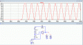
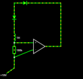
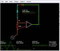
Please I need assistance in understanding this circuit. I read about this circuit in a paper, its meant to limit current in the diode connected to the inductor. The paper gave a vague circuit without giving any information on sizes of electronic element. In order to understand its behavior I decide to simulate the circuit with arbitrary values. It seems to be working but I dont understand how. An explanation of the circuit would be much appreciated.
The Op amp has a Max and Min Output of 15 and -15 v and a gain of 1K.
Thanks in advance for the help
Attachments
-
 31.7 KB Views: 25
 -
 88.4 KB Views: 24