 Facebook
 Google
 GitHub
 Linkedin
Hello! I'm new to this forum and joined in the hope to find people like me, who are interessted in repairing things and let other participate.
Maybe this is the totally wrong audience, so please be kind and tell me.
I'm highly interessted in any automotive electronics and also done some research and projects in this area. I also run a (German) website mk4-wiki.denkdose.de where i try to publish some of my solutions and backgrounds to it. I'm also a member in other electronics-communities but none of them is really handling this.
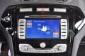
One of my current projects is to find out what causes the Blaupunkt (Bosch) "Travelpilot NX", which is build into many Ford vehicles, to shutdown after powering on. It just keeps running for some seconds and all seem ok, but then it shut off the display. After this, i can be pushed on two more times, where it does the same. Then it keeps off until power is pulled and put back again.
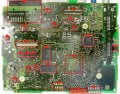
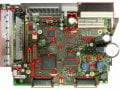
I've done serious research into that issue and also some repair tests. The system has two main components connected together, the mainboard and the graphicsboard. They can operate indepandently, so it is possible to pull the graphicsboard (with the touchscreen and buttons on it) and the mainboard will boot properly. Of course it is of no sense, because without the HMI one is unable to do anything with it. But it would communicate over CAN and would also play music of this is done while the Satnav is running. Funny, but very interesting for testing purposes!
So i found out the problem resides on the mainboard, because i swapped the graphicsboard to a working unit where it also works fine.
I can see on the current consumption of my switching power supply how it behaves. Also on the mainboard there is a HMI processor (OMAP5948) controlling all the funny stuff and a radio processor. They are coupled by an SPI interface or such. Also, those two components work more or less independant. So the HMI restarts when the display goes off, but the radio proc keeps running. This makes me pretty shure that the problem must be somewhere around the HMI proc. Maybe some sort of timeout causing the self reboot.
I've changed the RAM-Chips to be shure they are not faulty and causing this. Also changed the serial EEPROM, but this does'nt change anything either.
Next i tried to measure the power regulators, there are many of them for the various chips on the board. But the seem (!) okay.
So, if anyone is also into this topic and want to exchange his knowledge with me, be welcome!")
THX
Maybe this is the totally wrong audience, so please be kind and tell me.
I'm highly interessted in any automotive electronics and also done some research and projects in this area. I also run a (German) website mk4-wiki.denkdose.de where i try to publish some of my solutions and backgrounds to it. I'm also a member in other electronics-communities but none of them is really handling this.
One of my current projects is to find out what causes the Blaupunkt (Bosch) "Travelpilot NX", which is build into many Ford vehicles, to shutdown after powering on. It just keeps running for some seconds and all seem ok, but then it shut off the display. After this, i can be pushed on two more times, where it does the same. Then it keeps off until power is pulled and put back again.
I've done serious research into that issue and also some repair tests. The system has two main components connected together, the mainboard and the graphicsboard. They can operate indepandently, so it is possible to pull the graphicsboard (with the touchscreen and buttons on it) and the mainboard will boot properly. Of course it is of no sense, because without the HMI one is unable to do anything with it. But it would communicate over CAN and would also play music of this is done while the Satnav is running. Funny, but very interesting for testing purposes!
So i found out the problem resides on the mainboard, because i swapped the graphicsboard to a working unit where it also works fine.
I can see on the current consumption of my switching power supply how it behaves. Also on the mainboard there is a HMI processor (OMAP5948) controlling all the funny stuff and a radio processor. They are coupled by an SPI interface or such. Also, those two components work more or less independant. So the HMI restarts when the display goes off, but the radio proc keeps running. This makes me pretty shure that the problem must be somewhere around the HMI proc. Maybe some sort of timeout causing the self reboot.
I've changed the RAM-Chips to be shure they are not faulty and causing this. Also changed the serial EEPROM, but this does'nt change anything either.
Next i tried to measure the power regulators, there are many of them for the various chips on the board. But the seem (!) okay.
So, if anyone is also into this topic and want to exchange his knowledge with me, be welcome!
THX
Attachments
-
 51.8 KB Views: 47
 -
 592 KB Views: 61
 -
 406.2 KB Views: 60
Last edited by a moderator:


