Help needed to identify Guitar Amplifier Circuit component

Thread Starter

jikonn

Joined Dec 2, 2017
38
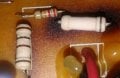
Hello to Everyone We have a guitar amplifier (chinese) based on LM1875T ...circuit board has some burning...on close inspection there are two components Im not sure what they are...some kind of capacitor ? i dont know...any help appreciated as I need to replace them in trying to get this amp working again.

Thanks in advance
 

Attachments

Last edited:

Dodgydave

Joined Jun 22, 2012
11,285
Resistors are small 22K 5%, and what looks like a 100 ohms, large burnt one. The all white one is probably the same 100 ohms, can you remove the resistors at one end, and measure them?
 

Thread Starter

jikonn

Joined Dec 2, 2017
38
Hi Dodgydave Thanks for your reply ...I removed (it fell off actually) the big white one with one band..using ohms rises in resistance from approx 20Megohm to Infiinity....reversing the leads has the effect happen again rising from about 20Megohm to infinity resistance... the one with four bands indeed reads 100ohms...I dont get what the one with the one band is ?
 

Thread Starter

jikonn

Joined Dec 2, 2017
38
That component with one band...appears to hold charge....after testing on ohms till OL...switch multimeter to Millivolt and get a descending Voltage from around 60mv... what on earth is it ? minimum initial resistance appears to be around 20megohm....the board seen is a combined Bridge Rectifier to the left....LM1875T in the middle and to the right is a 3 pin connector that goes to the guitar amps mixing ciruits..gain..tone..reverb...volume etc...the red/black wires goto 2 8ohm speakers.

the circuit to the right also includes two diodes..not sure if they are zener or signal ?? anyone confirm. TIA
 
There's the scorched diode and the scorched metal oxide resistor. That value should be the same as the other one.

The diode may be a standard diode if in the output stage.
 

Thread Starter

jikonn

Joined Dec 2, 2017
38
Posted as above close up of both sides of the board in the scorched areas....lookslike the symbol for a diode...the 3 pin connector that connects the Input/Mixer board can be seen from underside of board above - on the other end of this connector cable the input/mixer circuit connector pins are labelled +12v, GND, -12V...there are no markings on the diodes I can see... so could 1N4148 Signal Diode do as a replacement.?

the White (resistor?) with the one band fell off the board when testing..now testing it seems to be 'open circuit'! was getting some weird readings off it before it went open as said in my previous post...two comments say it is likely that it was a 100 ohm resistor...like its stable mate which is hanging by one leg still on the board.
 
Last edited:

Thread Starter

jikonn

Joined Dec 2, 2017
38
IMG_20171203_104636.jpg

Picture above from the 3 pin connector from the Input/Mixer board showing +12V Red, GND Blue, -12V White
 
Last edited:

Thread Starter

jikonn

Joined Dec 2, 2017
38
Anyone got Suggestions to what I could replace the scorched Resistors with..need something more robust than what has been used.
 

MrChips

Joined Oct 2, 2009
30,720
Reverse engineer the PCB and compare with a typical LM1875 application example.


Max supply voltage is 60V or ±30V.
What supply voltage are you feeding it? If you are feeding it with ±12V then you are safe.
Simply remove the two zener diodes and replace the burned out resistors with wire jumpers.
 

Thread Starter

jikonn

Joined Dec 2, 2017
38
Mr Chips thankyou for your reply.

the diodes are in circuit direct to the Input/Mixer Board. each diode has a 220uF cap next to.

Transformer secondary has 3 wires - printed on the transformer it says '21v x 2'...so assume 42vac and 21vac supplies the boards.

yes trying to work out what the scorched components exact purposes are?!..other than they seem to be interface with the input mixer board

confirming what you suggested....remove scorched diodes and replace scorched resistors with wire links..any risk at all with doing that....? my only concern is any potential to the mixer input board. Thanks again for your help.
 
Last edited:

Ylli

Joined Nov 13, 2015
1,086
The burned resistors are simply in series with the + and - power pins of the amplifier. For them to be burned would suggest the LM1875 might be fried. 100 ohms seems way to high for this application.

Someone else double check what I see on the power connector, two diodes, and two 220 uF caps. It looks to me like the caps are tied directly to the input pins on that power connector, and the diodes are anti-parallel to the caps to act as reverse polarity protection. That would mean that power connector should be getting +/- DC, not connected to the secondary of a transformer. The way everything in the area is burned I wonder if AC is being put into this connector.

Or since the caps appear OK, the power input polarity might be reversed (+ on the - pin, - on the + pin)
 
Last edited:

MrChips

Joined Oct 2, 2009
30,720
Sorry, I didn't see that there is a mixer board involved.
Can you post two sharp photos of the amplifier board, one from the top view and one from bottom view showing the full board?
I need to trace all the connections on the board.
Also I need to know what are all the wires/connectors to the board.
Where is the power supply board and what voltages come off the power supply?
 

MrChips

Joined Oct 2, 2009
30,720
The burned resistors are simply in series with the + and - power pins of the amplifier. For them to be burned would suggest the LM1875 might be fried. 100 ohms seems way to high for this application.

Someone else double check what I see on the power connector, two diodes, and two 220 uF caps. It looks to me like the caps are tied directly to the input pins on that power connector, and the diodes are anti-parallel to the caps to act as reverse polarity protection. That would mean that power connector should be getting +/- DC, not connected to the secondary of a transformer. The way everything in the area is burned I wonder if AC is being put into this connector.
Agreed.
Why would they put 100Ω on the power lines of the amplifier chip?
What is the purpose of the two diodes across the power lines?
Why are the diodes scorching the PCB?
 
Top