 Facebook
 Google
 GitHub
 Linkedin
Hi,
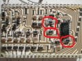
Hoping for some help identifying these 3 components that are poorly circled in the attached picture.
The device is from a 1982 Yamaha motorcycle and part of the Computer Monitoring System. They work in conjunction with the quad op-amp on the right side of the picture and the op-amp is misbehaving so I am trying to determine what these devices are. They do have a resistance value, two of which appear to be about 158K in circuit testing, the other is close to 1950 ohms, but once again in circuit measurement so may not be accurate. The resistance values are not sensitive to freeze spray so I think I have ruled out some type of thermistor.
I am most interested in the middle one, which appears to be in parallel with another 170K resistor of which the two are sourced by a 170K resistor with a 5V supply. The Vout is used as a reference voltage on the op-amp non-inverting pin and calculates with those values to be about 1.6 volts, but I am getting a reading close to 4.3 volts. The inverting side of the op-amp is switched between 0 and 5 volts, at which time the op-amp output pin should switch low, which it does not.
And just to add, that top one on the board with the funky looking solder on the left side is not unique, I am seeing that on several samples of this CCA.
Thanks in advance for any feedback
Attachments
-
 286.9 KB Views: 116


