I'm just in the thinking stages, if the idea is too absurd I'm not buying parts. I watched too many charred hotdogs and arc flash videos to put myself in danger.
I'm stuck on amps because.... I don't know. I'm just a bb EE you are correct I should talk about power electronics in terms of power. I thought current was the real challenge I needed to overcome
What makes the most sense is to drive the heaters with mains voltage and a much shorter duty cycle.Of course then there is the concern of mains connection to hardware that a person might contact accidentally. But higher voltage transistors, up to some point, are cheaper than higher current transistors. And the wires are thinner as well. And with variable duty cycle control and lower current in the on state, heat removal gets simple as well. Then if you go to alpha-numeric characters and character multiplexing the number of control devices gets a lot smaller. AND fewer interconnect wires. But much more complex control code.
So could the TS live with that concept???
What is the purpose of heating resistors? what is the objective here? reduce your "grid" to a smaller size, say 2x2 and then draw a circuit diagram, I have no idea what it is you're trying to do here. Is the heater distinct from the resistors or do you want to use the resistor array as a heater?
that is correct. but... why are you stuck on high amps? heat dissipation is measured in watts...
so 25W resistor can draw 5A if powered from 5V PSU. but it could also dissipate same heat when powered by 24V by drawing only just above an amp. lower current means smaller and easier to manage wires. you don't want to get into copper bars or really heavy PCB tracks.
Thank you for replying nicely, I'm learning and a lot of my learning happens when I learn the limits of what I'm trying to do. I really don't like forums, because people bring this ego with them. I appreciate your help!
i saw your picture but this is still not clear... just trying to think of possible logistics issues...
can you post some numbers? how far are they from each other?
how far is heater panel from control panel? what is the max temperature that heaters can produce? what is the environment?
you could run wires between two panels but that is going to be 242 conductors. there are multiconductor cables but that is also a thing to consider since you will need to derate more, since they are bundled together and mutually prevent each other from cooling. the next part is interconnect. common industrial plugs like Harting HAN will do but using 25c cables and connectors will still get you to some 10 cables or so.
i would look at any possible way to have PSU and MOSFETS close to heater panel. it is better to just run one AC power cable to PSU and forget all the external cabling and interconnects.
In your first post, you talk about having 5 A max to a grid of resistors, and then talk about 5 A per resistor. That makes sense only if all of the resistors that are "on" at one time are in series, which would be the case if you use PWM and only turn on one resistor at a time, but it also means that the maximum effective current you can get into each resistor (without playing games) would be 5 A divided by the number of resistors.
In a later post you say max wattage and voltage is 10 V / 3.5 A / 35 W. What is this for? Each resistor? The power supply? Each power supply (since you talk about multiple supplies)? Is that the rating, or what is actually needed?
In yet a later post, we discover that the grid is 11 x 11 and it is mentioned that all of the resistors might be on at the same time. Is this actually a requirement?
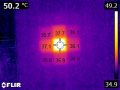
What ARE the actual requirements? What things do you have control over and what things are you stuck with? The resistors are being used as heaters. Okay. How much heat does each one need to provide? How fast do they need to respond? How fast do they respond? If they are slow enough, then you can use PWM to only provide power to a small number of them at a given time. But if they are too fast, then you would see that in your thermal image.
You talk about multiple supplies? Why multiple supplies? How many? What configuration? If you have one supply per row, then a simple strategy is to have each row be independent and cycle through the columns one at a time. That would let you give each resistor up to a maximum of about 9% duty cycle.
What you (seem) to be trying to do is either very easy or very difficult (or somewhere in between), depending on the constraints you have to satisfy.
In your first post, you talk about having 5 A max to a grid of resistors, and then talk about 5 A per resistor. That makes sense only if all of the resistors that are "on" at one time are in series, which would be the case if you use PWM and only turn on one resistor at a time, but it also means that the maximum effective current you can get into each resistor (without playing games) would be 5 A divided by the number of resistors.
In a later post you say max wattage and voltage is 10 V / 3.5 A / 35 W. What is this for? Each resistor? The power supply? Each power supply (since you talk about multiple supplies)? Is that the rating, or what is actually needed?
In yet a later post, we discover that the grid is 11 x 11 and it is mentioned that all of the resistors might be on at the same time. Is this actually a requirement?
What ARE the actual requirements? What things do you have control over and what things are you stuck with? The resistors are being used as heaters. Okay. How much heat does each one need to provide? How fast do they need to respond? How fast do they respond? If they are slow enough, then you can use PWM to only provide power to a small number of them at a given time. But if they are too fast, then you would see that in your thermal image.
You talk about multiple supplies? Why multiple supplies? How many? What configuration? If you have one supply per row, then a simple strategy is to have each row be independent and cycle through the columns one at a time. That would let you give each resistor up to a maximum of about 9% duty cycle.
What you (seem) to be trying to do is either very easy or very difficult (or somewhere in between), depending on the constraints you have to satisfy.
Okay let me clear up everything (Fanboying, because I've seen you on other post before)
- 5Amps per resistor
- I guess it is in series, Its hard to see it that way since every mosfet is getting its own gpio
In my head if they were in series and I tried to turn on 1 resistor, the rest would have no choice but to turn on.
- The 10V / 3.5A / 35 W is the calculation for 1 resistor by itself.
- It is a requirement to have all the resistors on at once. (as stated before, I like to push the boundaries. It helps me learn)
- Im going to skip this question
- I was using multiple supplies when I was taking an analog approach, now that I may use a controller. I will most likely only use 1 power source to the board for the mosfets (My drawing had shows that)
- It really depends on who you ask, I am learning.
I got stuck on the thermal isolation part, hardest design challenge is maintaining "contrast" - reducing thermal leakage between pixels.
The goal was to create images that are only visible using a thermal camera, so the max temp needs only to be ~65 Celsius.
For the heating part, my concept was to make each pixel like a floating MOS memory cell, each pixel would have a small capacitor that is refreshed by a row-column scan, the voltage on this capacitor determines how much power is dissipated by the pixel, which is fed constant 48Vdc. (low current = thinner wires = less IR heating leakage)
The drive electronics doesn't manage the power, just the refresh of each pixels stored charge.
the screen then has a common power plane, and a set of row and column lines to be scanned.
OK, so now we have a clue that the TS is wanting to present some sort of graphic images on the condensed fog on a glass block window.
There are quite a few challenges to doing that because it would require a lot of heat and the heat will spread and so the images will blur. So it is not likely that it can actually be done as desired, at anything close to a rational cost.
Your project seems like a fascinating undertaking. This kind of high-current application makes PWM with MOSFETs a wise decision. Given that MOSFETs generate significantly less heat during on and off switching than linear control using op-amps or BJTs, this method will effectively regulate the heat and limit the energy spent in the control elements.
You may achieve the desired thermal "image" by precisely controlling each heating element by using a microcontroller to regulate the PWM signals. Since dedicated heating elements are made to withstand high temperatures and may provide higher performance and endurance than resistors, they might be a superior option.
Additionally, if your "heat image" consists of a vast grid of pieces, integrating shift registers with an MCU or FPGA could aid in managing various outputs. This will make the design more scalable and straightforward.
I'm afraid the OP has not (IMHO) adequately explained what he wants to do, I've tried and studied his picture closely but it just makes no sense. He's also not answered several questions like are you seeking to use resistors as heat sources? If so surely the size and shape of the resistors is important so what are the desired dimensions?
Why not just use nichrome wire instead, its designed for heating rather than acting just as a resistor. To control the temperature of a length of the wire is trivial using PWM with a solid state relay - some can switch at 120 Hz so that's easily fast enough, the heater current could be AC or DC (if AC you could just use a variant of a dimmer switch design, a Triac).
 Facebook
 Google
 GitHub
 Linkedin

 you are correct I should talk about power electronics in terms of power. I thought current was the real challenge I needed to overcome