 Facebook
 Google
 GitHub
 Linkedin
Hi,
I am an electronics student designing my own lab power supply, and I need some help with a couple of things. My main concern is: does the concept look good enough to start building a prototype on a protoboard, and how do I calculate or estimate the capacitors so that the supply doesn't oscillate?
Main power supply components
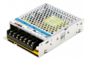
For my main DC power source, I will use a 220V-24V 108W LM100-20B24 switching power supply. I know that a toroidal transformer would be better, but I don't have the money to spend on one so i chouse this option. I want my power supply to have constant current (CC) and constant voltage (CV) modes of operation. I took inspiration from R. Lawrence's High Performance POWER SUPPLY UNIT and incorporated similar CC and CV regulation plus a couple of other things. The main difference in my design is that I will use a REF02 for my voltage reference and an ICL7660 for the negative voltage rail. The power transistor that I chose is the TIP120
Power supply design

My power supply will have two potentiometers: one to set the current limit and one to set the voltage. A diode from the output of U4 to the
non-inverting input of U1 is there to switch between CC and CV modes. I added capacitors to the feedback loop (known as an integrator) on the op-amps so that if the operator changes the potentiometer value, the op-amp output will change linearly instead of instantaneously and start resonating.
The output stage consists of a TIP120 power transistor and an NPN transistor that is meant to prevent faults from happening when the negative voltage rail decays (don't quote me on that one — I added this part from R. Lawrence’s circuit). Voltage is measured by a simple voltage divider, and current is differentially measured through a shunt resistor. The measurement signals are fed back to the inverting inputs of the op-amps.
Lastly, there is a CC mode indicator that consists of a simple PNP transistor and an LED.
If you have any advice or ideas to improve my design, feel free to drop a comment. If there are any questions, I will try to answer them as best as I can. I am thankful in advance for any advice.
This is actually my first post anywhere, so if there’s anything I could improve about the format or how I wrote it, I’d love to hear your feedback. Thanks!
Have a great day!
Domen
I am an electronics student designing my own lab power supply, and I need some help with a couple of things. My main concern is: does the concept look good enough to start building a prototype on a protoboard, and how do I calculate or estimate the capacitors so that the supply doesn't oscillate?
Main power supply components
For my main DC power source, I will use a 220V-24V 108W LM100-20B24 switching power supply. I know that a toroidal transformer would be better, but I don't have the money to spend on one so i chouse this option. I want my power supply to have constant current (CC) and constant voltage (CV) modes of operation. I took inspiration from R. Lawrence's High Performance POWER SUPPLY UNIT and incorporated similar CC and CV regulation plus a couple of other things. The main difference in my design is that I will use a REF02 for my voltage reference and an ICL7660 for the negative voltage rail. The power transistor that I chose is the TIP120
Power supply design
My power supply will have two potentiometers: one to set the current limit and one to set the voltage. A diode from the output of U4 to the
non-inverting input of U1 is there to switch between CC and CV modes. I added capacitors to the feedback loop (known as an integrator) on the op-amps so that if the operator changes the potentiometer value, the op-amp output will change linearly instead of instantaneously and start resonating.
The output stage consists of a TIP120 power transistor and an NPN transistor that is meant to prevent faults from happening when the negative voltage rail decays (don't quote me on that one — I added this part from R. Lawrence’s circuit). Voltage is measured by a simple voltage divider, and current is differentially measured through a shunt resistor. The measurement signals are fed back to the inverting inputs of the op-amps.
Lastly, there is a CC mode indicator that consists of a simple PNP transistor and an LED.
If you have any advice or ideas to improve my design, feel free to drop a comment. If there are any questions, I will try to answer them as best as I can. I am thankful in advance for any advice.
This is actually my first post anywhere, so if there’s anything I could improve about the format or how I wrote it, I’d love to hear your feedback. Thanks!
Have a great day!
Domen
Attachments
-
 131.4 KB Views: 3
 -
2.4 MB Views: 3
-
378.7 KB Views: 4
-
507.6 KB Views: 0
-
56.2 KB Views: 0
-
461.1 KB Views: 8


