Facebook
 Google
 GitHub
 Linkedin
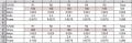
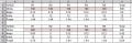
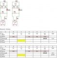
This is personal homework, not for school. I'm new to electronics and trying to create a spreadsheet to calculate my voltages needed for a specific outcome. I'm fine with calculating stand alone series or parallel DC but I'm having issues conceptualizing and creating a spreadsheet for the mixed circuit. In the circuit and spreadsheet below I am trying to create a spreadsheet that will allow me to put in different resistor values for R1, R2 and R3 and see the impact they have on O1 VDC input. Areas where I will plug in the resistor values are shaded. The Calculated area I need is in yellow. I have built this circuit on a breadboard and it does work fine, but I want to understand the math. I used variable resistors at first, and after the circuit was stable then I measured them and replaced them with normal resistors.
Here's my thought process:
R1 and O1 should be calculated in series?
R2, R3, and R4 should be calculated in parallel?
Then R1/O1 should be calculated and considered in parallel to R2, R3 and R4?
C1 is a 100 micro-farad electrolytic capacitor to filter out the noise caused by R4 piezo buzzer.
* PS2501 Optoisolator
** Piezo Buzzer 6V-24VDC
** Piezo Buzzer - .00625A measured with unit in series with mulitmeter at 12VDC
** Piezo Buzzer – 1920 Ohms calculated by R=I*E (R=.00625*12VDC)
TIA
Attachments
-
 47.5 KB Views: 24