Help creating a pcb

MrChips

Joined Oct 2, 2009
34,817
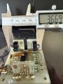
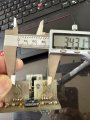
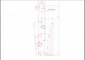
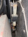
The distance between OPTO2 and OPTO3 is critical.

If you examine the graduation marks on the "ruler", what is the distance between two lines, centre to centre (or the distance between the 1st line and the 11th line and divide that by 10).

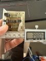
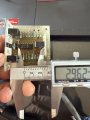
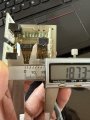
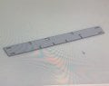
What is the spacing of the 4 pins of the opto-interrupter?
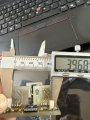
What is the spacing between pin-1 of OPTO2 and OPTO3?
What is the spacing between pin-1 of one OPTO and opin 4 of the other OPTO?
 

Thread Starter

Hadaak

Joined Jul 17, 2015
52
Graduation is in mm. The board is 60mm. Square board. Sorry I don’t understand the graduation question !
I tool pics for the other dimensions.
space between the optos is 2.60mm.
 

Attachments

MrChips

Joined Oct 2, 2009
34,817
I need the distance between the OPTO2 and OPTO3 pins as measured by the locations on the pads on the main board.
Note, I am not mounting the physical OPTO boards for you. I only need to locate where the solder pads go on the board.

By "graduations" I mean the spacing of the lines or grid on the "ruler" that slides in the slots of OPTO2 and OPTO3.
OPTO2 and OPTO3 must be positioned to a non-integer multiple of the ruler grid.
 

Thread Starter

Hadaak

Joined Jul 17, 2015
52
Guess what ! I removed opto 3 and replaced it with opto 1 and now opto 3 works fine. And opto 1 does not change voltage state. The output of its wire stays at 23v. So I guess a new opto will do the trick. I don’t have the ruler right now. I will get you some pics later tonight. And I will upload the other dimensions. I will also order a pack of optos to replace the bad one while waiting for the new board.
 

MrChips

Joined Oct 2, 2009
34,817
Guess what ! I removed opto 3 and replaced it with opto 1 and now opto 3 works fine. And opto 1 does not change voltage state. The output of its wire stays at 23v. So I guess a new opto will do the trick. I don’t have the ruler right now. I will get you some pics later tonight. And I will upload the other dimensions. I will also order a pack of optos to replace the bad one while waiting for the new board.
This is ambiguous and confusing.

You removed physical OPTO3 and put OPTO1 in its place.
As I read it, physical OPTO1 in its new location is not working. Hence the problem is not with the opto but with the circuitry?

Please clarify.
 

Thread Starter

Hadaak

Joined Jul 17, 2015
52
No. Opto 1 in physical location of Opto 3 is working as expected. Block/unblock ok. Voltage change from 23v to 2v when blocked then back to 23v when unblocked.
opto 3 in physical location of Opto 1 is stuck at 23v.
So issue is with opto 3. But opto 1 in new location might die too some day in this board.
 

MrChips

Joined Oct 2, 2009
34,817
Can you give me the big picture?
Tell us in what instrument this is used. Show us a photo of how the opto board is mounted on the instrument along with the ruler.
I need to know the purpose of the ruler.
 

Thread Starter

Hadaak

Joined Jul 17, 2015
52
This board is used in a hydraulic metal shearing machine. Amada GPX series. The controller board uses this daughter board to search for selectrd height position. I will post a picture later today.
When opto 1 is blocked machine moves up or down. When opto 1 is unblocked machine determines positions based on which of the other optos is unblocked. It has three position 1 2 4. These positions are mapped to the three wires red/green/yellow going back to the motherboard. Unblocked state voltage is 23. Blocked voltage state is 2v.
 
Last edited:

MrChips

Joined Oct 2, 2009
34,817
Ok. That makes sense now. I had wrongly assumed that the optos were quadrature encoders. They are not quadrature encoders. There are no grid lines on the ruler. Hence their placements are not as critical as I had thought.
 

Thread Starter

Hadaak

Joined Jul 17, 2015
52
No I didn’t. I will test tomorrow. Opto 3 (bad) is now in opto 1 location. The thing now is it does not change state from 23v to 2v. It stays stuck at 23v. Blocked or unblocked does not matter. Or I probably fried with when I desolder it.
 

MrChips

Joined Oct 2, 2009
34,817
As far as I can see, the symptom is that the LED emitter in OPTO3 is aging and losing optical efficiency.
The feedback resistor in location for OPTO1 is R12. If you remove R12 the opto should start working.
If it does, try changing the feedback resistor R12 from 100 kΩ to 220 kΩ or 330 kΩ. (For this application, you don't need any hysteresis.)
 

MrChips

Joined Oct 2, 2009
34,817
Just so you know, you went to a lot of trouble posting photographs of the dimensions of the opto-interrupters and locations of the boards, etc. All of these are not of any use to me.

What is much more critical are the locations of the four mounting holes and the location of the solder pads of the opto-interrupter boards relative to the mounting holes and with respect to the edges of the board.

Note also pins on DIP packages and many components are usually on 0.1 inch grid.

When laying out a PCB, you have to make a decision to stick with inches or mm. Since many components are already on inch grid, that is the unit of choice in most cases.

If the component pins are on mm spacing then you would do the layout on a mm grid. Otherwise it complicates the task when you have to constantly convert from inches to mm.

In reality, the pad spacing of thru-hole components such as resistor, capacitors, diodes, etc. does not matter since you can bend the leads to fit the board. If you are using pick-and-place PCB automated assembly, then you have to stick with common dimensions. The pin spacing of all components are determined in the CAD library model so that is not a problem. What is more critical in your case is the relative distance of the opto-interrupters and the mounting holes.

Was the original PCB layout done using a metric grid since it originated in France?
To find out, measure the distances between pads and see what fits best, mm or 0.1".
 

Thread Starter

Hadaak

Joined Jul 17, 2015
52
Sorry MrChips. Couldn’t get back to you earlier. And didn’t get the usual notifications
I will get you the info you need for the pcb. And will also test removing the resister as per your instruction. And yes the board and the manufacturer of the machine are french. So mm it is
 
Last edited:

Thread Starter

Hadaak

Joined Jul 17, 2015
52
So I got the new 5 pieces pack of optos. When desoldering opto 3, which is now in physical location of opto 1, I found out I had reverse-soldered it ! I soldered it back correctly and it worked. But then opto 2 started sticking open (output 2v). I replaced it with a new opto and now all optos are working as expected. I haven’t put the board back on the machine to test. I will do that on the weekend.
I am adding the board dimensions. Please let me know if you need more info. Dimensions are in mm.
Thanks !
 

Attachments

Top