In any case, R8, R9 and R18 should be replaced regardless of the resistance reading.
Try replacing R8 alone with 2k2Ω 1/2W resistor instead of 1k and see if this works.
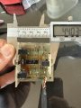
So I hooked up the board to an external 24v power supply. No modifications/repairs done to the board yet. Now I see both opto 2 and 3 get stuck when blocked !!
So I replaced all three 1k resisters. Opto 1 and 2 are working fine. But Opto3 still gets stuck a 2v when blocked. I put a 2.2kohm resister on it and it shows 2v when the board is powered up and stays stuck at 2v. Blocking or unblcking does not change anything. I put back a 1k resister and it powers up with 23v but still gets stuck at 2v when blocked.
On the output wires:
Green = opto1 = number 1
Red = opto2 = number 2
Yellow = opto3 = number 4
the wires on the board are as follows:
G
4
2
1
V
There is no num 3.
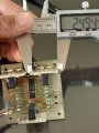
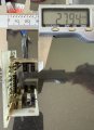
I connet the voltmeter + line on the V pin of the board and the common wire to one of the three output wires to test output voltage change. Default unblocked opto is 23.3v for all three optos.
Connect the -ve lead (BLACK) of the DMM to the negative side of the capacitor C1.
Use the +ve lead (RED) of the DMM for all measurements.
There will be four voltage readings to take at each step, measurements at TP1, TP2, TP3 and the positive side of capacitor C1 which we will call Vcc. Record the readings in a table:
Vcc TP1 TP2 TP3
Step 1 - measure after power ON
Step 2 - measure with TP1 blocked
Step 3 - measure with TP1 unblocked
Step 4 - measure with TP2 blocked
Step 5 - measure with TP2 unblocked
Step 6 - measure with TP3 blocked
Step 7 - measure with TP3 unblocked
There will be be more tests to come after this series of tests.
since resistors appear to be all 1/4W, one obvious problem are the 1k value resistors (R8, R9 and R18). with those components, board should not be powered by more than 15V or those three resistors WILL burn. if you want circuit to work at 24V without burning, replace those three resistors either by 2.2k ... or... use 1K resistors that are at least 600mW.
you can measure voltage directly across each of them. suppose you read 22V. then (22V)*(22V)/(1000 Ohm)=0.484W or 484mW. this is the heat that each of the resistors is dissipating continuously. that is twice as much as they are supposed to sweat off since they are only rated for maximum of 250mW.
and since they are crisped, they may experience all sorts of problems, including intermittent operation.
so where did the 22V come from?
your circuit is powered by 24V. about 0.7V is dropped by diode used to ensure correct polarity. each opto has internal LED, since emitting visible light is normally not required, their Vf is usually about 1.2 - 1.3V.
so resistor see whatever is left: 24V - 0.7V -1.3V = 22V.
there are different tests you can do. the simplest one is to measure voltage across each of those resistors. if you measure a boit less than supply, they must be working. if you measure zero, resistor is short or opto sender is open (burned out). if you measure same voltage as supply (24V) then resistor is open or opto is shorted.
you can also try testing rest of the circuit by temporarily chorting C and E of the opto. if rest of the circuit works, output will change. by ruling the rest of the circuit out, you know that problem is opto or biasing resistor R8. either way, both opto and R8 need to be replaced
Assuming that Vcc = 22 V, the bias resistors would bring the non-inverting input to 1/2 Vcc = 11 V.
However, there is feedback from the output.
When the output is low, the bias is 7 V.
When the output is high, the bias is 15 V.
The inverting input has to fall below 7 V for the op amp output to switch to HIGH.
The inverting input hast to rise above 15 V for the op amp output to switch to LOW.
We can see that the voltages associated with OPTO3 are different from those at OPTO1 and OPTO2.
Remove POWER and measure the resistances of R3, R4, and R5 while they are in-circuit.
Then remove R3 and measure it out of circuit.
With R3 removed, repeat the test on OPTO3 only as follows:
Measure voltage at TP4 and at LM324 pin-14 (follow the schematics, basically we want the measure the voltages on both legs of R3 where R3 would have been, i.e. the non-inverting pin-12 input and the output pin-14)
1) on initial power on, OPTO3 unblocked
2) OPTO3 blocked
3) OPTO3 unblocked
Also, note the following must be done at some point:
The 1N4007 diode feeds Vcc from 24 V.
Vcc @ 22 V puts the voltage across the diode at 2 V this is too high. Replace the diode, any diode in the 1N4001-4007 series.
It’s getting a bit tricky to work with the board. The board is very old and the tracks are very brittle. I will order a new one online. It will take a week or so to get here. I will import your schematics to an online pcb service and will certainly need your help to tune the board. Thanks again
That would be great. The current board has four parts. The main board and the three small board for the photointerrupters. Not sure how you can add that to the gerber. I will give you the exact dimensions so that the ruler that goes inside the optos fits in the new board.
thanks again for your help !
 Facebook
 Google
 GitHub
 Linkedin