Help Converting Control Block to C Code

Thread Starter

lindula

Joined Sep 23, 2016
94
Hello, I have the a Control Block that I need to implement in C code.
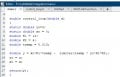
continuous.jpg
Here is my math:
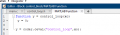
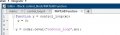
Y(s) = K1 E(s) (1/s)
E(s) = X(x) - K2 Y(s)

Now put E(s) in Y(s)

Y(s) = K1 (1/s)(X(s) - K2Y(s))

Y(s) = K1(1/s)X(s) - K1K2X(s)Y(s)

y(t) = K1 x(t) y(t-1) - K1K2 x(t) y(t)

I know my math is not right but can anyone help me please? If I can get y(t) I should be able to get in C code.

Thanks,
Joe
 

Attachments

Thread Starter

lindula

Joined Sep 23, 2016
94
Hi, I've made some progress.
SDomain.jpg
If I take the Inverse Laplace I get an exponential in the y(t). Is the a why I can avoid using an an exponential?

I needed to add in a Saturation Block in the feedback path.
Integrator.jpg
There mus be a simple why one could convert the block to a C program.
 

bogosort

Joined Sep 24, 2011
696
The transfer function can be written simply as \[ \frac{Y(s)}{X(s)} = \frac{K_1}{s+ K_1 K_2} = \frac{2}{s + 6} \] Therefore, \[ Y(s) = \left(\frac{2}{s + 6}\right) X(s) \] and so \[ y(t) = 2e^{-6t} x(t) \] As this is a function of continuous time, what you do next depends on your specific application. Presumably the input x is a sampled signal, and so you could simply evaluate y at the given sample points.

If you need a more general solution in the discrete domain, you can work from the z-transform of the transfer function. Alternatively, you can express y as a differential equation in the time domain, and then derive an appropriate difference equation that can be implemented in C.
 

Thread Starter

lindula

Joined Sep 23, 2016
94
The transfer function can be written simply as \[ \frac{Y(s)}{X(s)} = \frac{K_1}{s+ K_1 K_2} = \frac{2}{s + 6} \] Therefore, \[ Y(s) = \left(\frac{2}{s + 6}\right) X(s) \] and so \[ y(t) = 2e^{-6t} x(t) \] As this is a function of continuous time, what you do next depends on your specific application. Presumably the input x is a sampled signal, and so you could simply evaluate y at the given sample points.

If you need a more general solution in the discrete domain, you can work from the z-transform of the transfer function. Alternatively, you can express y as a differential equation in the time domain, and then derive an appropriate difference equation that can be implemented in C.
Hello, thank you for responding to my message. I've updated my Simulink model:
Integrator2.jpg
I added the Discrete integrator blocks

Here is my math:
Cacl.jpg
Is my Difference Equation correct? I want to implement this in C code.

Thank you,
Joe
 

Thread Starter

lindula

Joined Sep 23, 2016
94
Hello, thank you for responding to my message. I've updated my Simulink model:
View attachment 210927
I added the Discrete integrator blocks

Here is my math:
View attachment 210928
Is my Difference Equation correct? I want to implement this in C code.

Thank you,
Joe
I've made some progress. Here my my models in Simulink:
control_loops.jpg
Plots zoomed out:
Plot1.jpg

The top plot is the outputs of my C function that implements the Difference Equation from my math above. The input to the function I call Motor Drive where a positive step would drive the motor clockwise and a negative step drives the motor in the counter-clockwise direction. The bottom plots of the S-Domain and Z-Domain plots.

Here I zoom in a little. My model shows a very fast rise time and I believe this is because of the type of Solver I have set in Simulink it is set to Variable-step. If I change the Solver to Fixed-Step my model's plot looks better but the Continuous time goes crazy. I probably should have a separate Simulink project with just the Z Domain and my function.
plot2.jpg
Now I will include the views of how to add the C code into matlab:
My C Code that tries to implement a control that would take in a motor drive command and it's final position.

main_c.jpg

Header file:
header.jpg
Matlab Function:
matlab_function.jpg
 

Attachments

Thread Starter

lindula

Joined Sep 23, 2016
94
I've made some progress. Here my my models in Simulink:
View attachment 211321
Plots zoomed out:
View attachment 211322

The top plot is the outputs of my C function that implements the Difference Equation from my math above. The input to the function I call Motor Drive where a positive step would drive the motor clockwise and a negative step drives the motor in the counter-clockwise direction. The bottom plots of the S-Domain and Z-Domain plots.

Here I zoom in a little. My model shows a very fast rise time and I believe this is because of the type of Solver I have set in Simulink it is set to Variable-step. If I change the Solver to Fixed-Step my model's plot looks better but the Continuous time goes crazy. I probably should have a separate Simulink project with just the Z Domain and my function.
View attachment 211323
Now I will include the views of how to add the C code into matlab:
My C Code that tries to implement a control that would take in a motor drive command and it's final position.

View attachment 211327

Header file:
View attachment 211330
Matlab Function:
View attachment 211329
In Simulink go to Model Settings > Simulation:
Properties.jpg
 

Thread Starter

lindula

Joined Sep 23, 2016
94
I think I'm making progress. I can remove the S Domain block and change the Solver to Fixed step and I'm hoping that my C code will resemble the Z domain. Anyways, its been fun.

I'm not an expert that this.
 
Top