Help converting an "asm" file over to HEX for a PIC12F508 ic

Thread Starter

Flash001USA

Joined Nov 27, 2020
15
I don't think the original full user guide manuals are still available for the MPLAB-IDE but if you punch in a search on the Microchip web site using the original part No's, you do get some helpful publications for using the older MPLAB-IDE.
Search Using DS33014 & DS51519, the latter has some of the older manual at the end.
Max.
Thank you for the feedback.
 

Thread Starter

Flash001USA

Joined Nov 27, 2020
15
Yes, I use MPLab 8.92 (ASM v. 5.49). It is called a whole "tool suite." 8.92 is no longer supported, but those who write Assembly use to prefer it to the early version of MPLabX (ASM v.5.77 or so). If you use chips from the last couple of years, you have no choice but to use the later software.

I don't have the latter program even installed as I use an older series of chips (PIC16F1xxx) that are known as enhanced midrange. The chips you are using are baseline. They have a slightly fewer instructions, and they do not have interrupts. The 12F6xx and 12F1xxx are midrange and enhanced midrange respectively . They have interrupts. The chips are often identified by their "core" size. Yours are 12-bit, midrange are 14-bit, and the PIC18F chips are 16-bit. The core size affects programming and memory access. All of the chips I have mentioned are 8-bit devices and in general, the memory registers are just 8-bit.

I started with the 12F508/509 series and quickly migrated to the 12F6xx and later devices. The only advantage I see to baseline chips is the set-up is simpler as there are not as many options to chose. Countless tutorials on the web for programming; although, Assembly is not very popular today. In the early part of this century, it was more common.
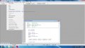
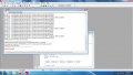
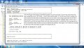
John I upgraded to MPLAB ver 8.92 but I was unclear about "ASM v. 5.49" Is this a plugin for the program? I looked all over their website for this file and could not find it in the archives. The install went with zero errors and I did try my hand at the program following your steps but with no luck. Rather than trying to exolain the steps I did I took screenshots along with adding some text explaining what I did. Hopefully I just made a simple misstep and you will spot it. I am sorry for picking your brain but I know you will see my error and hopefully put me on course.
 

Attachments

JohnInTX

Joined Jun 26, 2012
4,787
The assembler is standard in MPLAB 8.x Photo 3 says it is working but you need to tweak the code.

Add the code shown in lines 4,5, and 6 below. The basic code doesn't expect the 12F508 so it doesn't know to include the file that has the processor register descriptions for the assembler.
You can just remove the 'list' lines. They are redundant here and will generate a Processor Mismatch error if not commented out or deleted.

Don't forget the manuals linked in #20.
It should assemble OK.
Code:
;    list p=12f508A            ; <---- you don't need these, comment out with a semicolon or delete
;    list p=12F509A

    ifdef __12F508             ;<---- add these 3 lines - copy/paste to the source
     include "p12F508.inc"
     endif                    


     ifdef __12C508A
     include "p12c508a.inc"
     endif
     ifdef __12C509A
     include "p12c509a.inc"
     endif
 
Last edited:

jpanhalt

Joined Jan 18, 2008
11,087
John let me ask you a question: I just figured out that this circuit times out after 5 minutes of inactivity. I figured this out a few hours ago and at first I thought I was losing my mind till I timed it at which point it led me to the asm file where I thumbed through it and seen what appeared to be a line displaying a timeout after 5 minutes of inactivity meaning that it would shut down until the switches were toggled. I pasted that part of the asm file below. The timeout is listed in two places. Can changing what these lines have typed in them tell it to always stay on and if not, can the time be changed to tell the program to stay on for hours instead of minutes? I placed a "<----------" next to the two lines I found discussing time. I really did NOT want to come here and bother you with this again. Also I have MPLAB ver 8.10 and it looks close to what you are running and I was working with it using your notes but I still had issues trying to convert the file over so it may be the version is slightly different that what you are using.
Yes, one could go through the entire source code, find TIMEOUT, and figure out how to bypass it. It would probably be easier to do that and set to hours. Note TIMEOUT is defined as the product of 100 and 300 = 30,000 "clicks" of the clock in 0.01 seconds. The system clock runs at 4 MHz/4 = 1 MHz = 1 us per "tick." 30,000 us = 30 ms = 0.03 seconds. 5 minutes is 300 seconds. So somewhere in the code is a delay for a count of 10,000, or something like that.

Such long periods usually execute loops within loops, like this:
Code:
 Source: http://www.piclist.com/techref/piclist/codegen/delay.htm
; Delay = 300 seconds
; Clock frequency = 4 MHz

; Actual delay = 300 seconds = 300000000 cycles
; Error = 0 %

    cblock
    d1
    d2
    d3
    d4
    endc

            ;299999995 cycles
    movlw    0x54
    movwf    d1
    movlw    0xA1
    movwf    d2
    movlw    0xFD
    movwf    d3
    movlw    0x02
    movwf    d4
Delay_0
    decfsz    d1, f
    goto    $+2
    decfsz    d2, f
    goto    $+2
    decfsz    d3, f
    goto    $+2
    decfsz    d4, f
    goto    Delay_0

            ;5 cycles
    goto    $+1
    goto    $+1
    nop
PICList.com is a great resource for Assembly code. It is a bit dated, but still very useful.

The code you have needs to be looked at. Although will it will not need to be analyzed in detail, simply deleting a delay could cause problems. One needs to find the context for how the delay is called and deal with it there. Alternatively, if the delay code is something like the code posted just above, one could change the constants to make it run longer. The former approach might be better.

Re: ASM version
MPLab is a suite of programs and files. The ASM version that is incorporated in MPLab 8.92 is shown in release notes:
1606638054712.png
 

jpanhalt

Joined Jan 18, 2008
11,087
Perhaps it is not too hard, if you don't mind code with some broken parts. The sleep command seems to come from here:
Code:
loop8     incf note,w                   ; silent ?
          bnz main_loop                 ; branch if not

          movlw SAMPLE1/d'10'
          btfsc mode,0
          movlw SAMPLE2/d'10'
          subwf timer+1
          skpc
          decf timer+0

          btfsc timer+0,7               ; sleep if timeout
          goto power_down

          goto loop0
The critical part is when it tests the timer+0 register bit<7> for being set (btfsc). When that bit gets set, it goes to the subroutine, "power_down." That opens a few options. Immediately upon going to that routine, you could go to "loop0, " which is probably the start. An alternative is to comment out the "goto poweer_down" like this:
Code:
movlw SAMPLE1/d'10'
          btfsc mode,0
          movlw SAMPLE2/d'10'
          subwf timer+1
          skpc
          decf timer+0

;          btfsc timer+0,7               ; sleep if timeout
;          goto power_down

          goto loop0
That change will cause it to ignore "timer+". I don't know for sure what letting timer+ just keep running will do. Probably nothing.

Disclaimer: I am not responsible for any damages, physical and/or mental, including and not limited to consequential damages, for allowing this theremin to run continuously. In other words, for example, if your cats climb the walls and/or your wife divorces you, it's not my fault. ;)
 

Thread Starter

Flash001USA

Joined Nov 27, 2020
15
Perhaps it is not too hard, if you don't mind code with some broken parts. The sleep command seems to come from here:
Code:
loop8     incf note,w                   ; silent ?
          bnz main_loop                 ; branch if not

          movlw SAMPLE1/d'10'
          btfsc mode,0
          movlw SAMPLE2/d'10'
          subwf timer+1
          skpc
          decf timer+0

          btfsc timer+0,7               ; sleep if timeout
          goto power_down

          goto loop0
The critical part is when it tests the timer+0 register bit<7> for being set (btfsc). When that bit gets set, it goes to the subroutine, "power_down." That opens a few options. Immediately upon going to that routine, you could go to "loop0, " which is probably the start. An alternative is to comment out the "goto poweer_down" like this:
Code:
movlw SAMPLE1/d'10'
          btfsc mode,0
          movlw SAMPLE2/d'10'
          subwf timer+1
          skpc
          decf timer+0

;          btfsc timer+0,7               ; sleep if timeout
;          goto power_down

          goto loop0
That change will cause it to ignore "timer+". I don't know for sure what letting timer+ just keep running will do. Probably nothing.

Disclaimer: I am not responsible for any damages, physical and/or mental, including and not limited to consequential damages, for allowing this theremin to run continuously. In other words, for example, if your cats climb the walls and/or your wife divorces you, it's not my fault. ;)
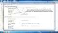
John here's an update: All is well with the code universe. I attached a few photos to explain what I did... It works!
 

Attachments

Last edited:

BobaMosfet

Joined Jul 1, 2009
2,211
Hi I am searching for someone who can help me with converting an open source assembly code "asm file" over to a hex file for a PIC12F508 ic. I'm retired from the electronics field and I do not have the knowledge or proper training to convert this file over myself. I did try my hand at MPLAB ver 8.xx but I'm spinning my wheels and driving blind with this process. A bit about me: I come from the wild world of analog electronics repair along with some with digital troubleshooting skills but unfortunately I do not possess skills for actual programming and this is something that I rarely ever do and when I have programmed ic's in the past it was with pre-written ready to go HEX files for open source projects. I'm in the process of trying to learn this skill but it's going to take me a while to absorb this and in the meantime I'm hoping to find someone who can help me with this conversion. Any help whatsoever would be greatly appreciated. Once again, this is open source code so there are no restrictions to using this code. Thank you.
Just for edification- An '.asm' file is an assembly language text file. In order to convert it to an OBJECT (hex) file, you need to run it through the Assembler that it was originally written with. An Assembler takes the text file, checks it's syntax, identifies all labels, addresses, pointers and so forth, builds a symbol table to hold all that, then calculates all addresses, relative, and direct and 'links' this altogether with a linker (adding stubs as necessary), and turns this into a binary file (object file) that can have a .obj or .hex extension for direct load into the processor/micro-controller for which it was originally intended to execute on.

Good luck in your journey.
 

Thread Starter

Flash001USA

Joined Nov 27, 2020
15
Just for edification- An '.asm' file is an assembly language text file. In order to convert it to an OBJECT (hex) file, you need to run it through the Assembler that it was originally written with. An Assembler takes the text file, checks it's syntax, identifies all labels, addresses, pointers and so forth, builds a symbol table to hold all that, then calculates all addresses, relative, and direct and 'links' this altogether with a linker (adding stubs as necessary), and turns this into a binary file (object file) that can have a .obj or .hex extension for direct load into the processor/micro-controller for which it was originally intended to execute on.

Good luck in your journey.
Hey thank you for the reply. Yeah has been interesting for me to say the least. I was able to get in there and not only generate the hex file that I needed but I was also able to edit the ASM file to do exactly what I needed it to do. This is something I should have learned a long time ago but never did because my job was all hands on repairing and/or basic designing along with upgrading projects. Now that I'm retired I want to take it on for the fun and the challenge of learning this. I can't thank everybody enough who stepped up to point me in the right direction.
 

jpanhalt

Joined Jan 18, 2008
11,087
The chips you are using are two of the simplest Microchip offerings. If you decide to move on with 8-bit stuff, I suggest the enhanced midrange (e.g., 12F1840 and 16F1xxx ). I use the 16f1829 as default, but if I need more pins, I use another 16F1xxx. Sixteen bit core (18Fxxxx) and 16-bit chips (e.g., PIC24F) are a big step. You probably do not need them. We went to the moon with much less.
 

Thread Starter

Flash001USA

Joined Nov 27, 2020
15
The chips you are using are two of the simplest Microchip offerings. If you decide to move on with 8-bit stuff, I suggest the enhanced midrange (e.g., 12F1840 and 16F1xxx ). I use the 16f1829 as default, but if I need more pins, I use another 16F1xxx. Sixteen bit core (18Fxxxx) and 16-bit chips (e.g., PIC24F) are a big step. You probably do not need them. We went to the moon with much less.
" We went to the moon with much less." That should be on a Tee-Shirt... lol!
 

hcape

Joined Aug 29, 2012
1
I have uploaded the hex file as .hex and .txt

I would not recommend using that chip. It is one-time programmable. That may be why your programmer doesn't list it. What programmer do you have? You canchange the processor to 12F508A or 12F509A and it may work.
How would I use this asm & Hex with a 16f84 chip insted of the 12C508A? would you send me instructions on that Thank you!
 
Top