Help, Building Lab power supply.

Thread Starter

Gilad123

Joined Jun 20, 2020
3
Hello,

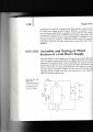
I'm new to electronics and I'm using Randy Slone book "guide to understanding electricity and electronics" to build a lab power supply.
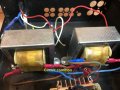
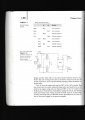
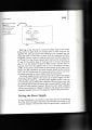
I got to the bridge rectifier testing stage and run into problems. The books uses two 10Kohms resistor to measure the DC and AC voltage after the rectifier (see below image). When I measure the DC voltage on the resistors I get same results as in the book, namely, 24v and -24v. When I measure the AC voltage I get 50v on one of the resistors and 0 on the other, while according to the book I should get 12v on each one of them.
I tried using another rectifier and got the same results.
Anyone has an idea what I'm doing wrong?
 

Attachments

dl324

Joined Mar 30, 2015
16,845
Welcome to AAC!

You can't measure pulsating DC with a DVM. You need an oscilloscope.

Can you post the text for the experiment to make sure nothing important was overlooked?

When I measure the AC voltage I get 50v on one of the resistors and 0 on the other, while according to the book I should get 12v on each one of them.
Where is the ground lead for the meter and where are you taking the measurements? Regardless, you can't measure pulsating DC with the AC setting on a DVM. It expects to see a sine wave.

It seems to me that you need a better book.
 

crutschow

Joined Mar 14, 2008
34,282
When I measure the AC voltage I get 50v on one of the resistors and 0 on the other, while according to the book I should get 12v on each one of them.
The two resistors should measure the same voltage to ground.
If not, then I suspect a wiring error.
 

Papabravo

Joined Feb 24, 2006
21,159
Most of the Bridge Rectifiers I have ever seen have the AC terminals on the same side or the same end to facilitate PCB layout. I have never seen an IC that was configured to make schematic drawing easier.
 

DickCappels

Joined Aug 21, 2008
10,153
You should not be getting oV out of either output. Either there is an error in wiring or a bad component. When you have solved that problem, place a capacitor (10 uf to 100 uf should do it) and the voltages you measure should be 1.414 times the peak voltage.
 

Papabravo

Joined Feb 24, 2006
21,159
You should not be getting oV out of either output. Either there is an error in wiring or a bad component. When you have solved that problem, place a capacitor (10 uf to 100 uf should do it) and the voltages you measure should be 1.414 times the peak voltage.
Once the capacitor is there they will essentially be measuring the peak voltage minus the "droop". 1.414 or SQRT(2) is the scale factor from RMS to peak.
 

AnalogKid

Joined Aug 1, 2013
10,986
As above, check your wiring. Note that the three Ground symbol points must be connected together.

Also ...

Unless the book makes it clear what the author is using, different digital multimeters are notorious for giving all kinds of different readings for the "same" thing. This is largely because they use different methods to measure AC. Internally, the meter has one function - measuring a DC voltage potential. Everything else (amps, ohms, AC, whatever) is based on converting the input signal to a representative DC voltage and measuring that. A cheap meter measures AC by half-wave rectifying it to pulsating DC, filtering it a little bit to remove some of the ripple, attenuating it by 29%, and presenting that DC voltage to the meter section. The 29% attenuation is an approximation of the ratio between an AC sinewave waveform's peak and RMS values (1 / (sqrt 2), or 0.7071). This gets into the math of AC, something you might not be ready for just yet. Bottom line - your results may vary, but not by 50 V. Check your wiring.

ak
 

Thread Starter

Gilad123

Joined Jun 20, 2020
3
Thank you all for your reply's and help in this matter!

I attached the full text explaining the measurement part.
I also suspect the ground lead for the meter but didn't know how to check it. The book specify "circuit common" between the serial connection of the transformers secondary's. The circuit common is the "ground" for the resistors and for the DVM (and later for the capacitors). The "circuit common" term was not clear to me and what I did is to add a connection point between the serial connection of the two transformers secondary's (see picture).

Another information that might help - I continued with the assembly and replaced the resistors with capacitors (and connected them also to the "circuit common"). The DC voltage reading was exactly according to the book (34 v) but the AC was 80v on each of the capacitors while the book specify that is should be 5-20 mV... at this point I stopped and went for help.

Any idea what I did wrong?

Gilad
 

Attachments

dl324

Joined Mar 30, 2015
16,845
clipimage.jpg
The DC voltage reading was exactly according to the book (34 v)
Where is 34V mentioned? I only saw "about +/- 24V". Are you using a transformer supplied with the book? If not, you can't expect to get exactly the same voltages as the author.
but the AC was 80v on each of the capacitors while the book specify that is should be 5-20 mV...
You're not interpreting the text correctly and the author isn't describing what you're measuring correctly. He said you're going to get an RMS voltage for the AC component. That's not correct. How a DVM measures AC when it isn't a sine wave depends on the meter.

You're not going to be able to measure ripple voltage unless you have an oscilloscope.

EDIT: add image showing ripple voltage on full wave rectified output.
clipimage.jpg
The dotted line represents the rectified output without a filter cap. The ripple voltage is with a filter cap and it's amplitude depends on the load. With no load, there could be very little ripple.

I don't know what the picture was intended to show. It was just an image that showed up in a search.
 
Last edited:

Thread Starter

Gilad123

Joined Jun 20, 2020
3
View attachment 213768Where is 34V mentioned? I only saw "about +/- 24V". Are you using a transformer supplied with the book? If not, you can't expect to get exactly the same voltages as the author.
You're not interpreting the text correctly and the author isn't describing what you're measuring correctly. He said you're going to get an RMS voltage for the AC component. That's not correct. How a DVM measures AC when it isn't a sine wave depends on the meter.

You're not going to be able to measure ripple voltage unless you have an oscilloscope.

EDIT: add image showing ripple voltage on full wave rectified output.
View attachment 213769
The dotted line represents the rectified output without a filter cap. The ripple voltage is with a filter cap and it's amplitude depends on the load. With no load, there could be very little ripple.

I don't know what the picture was intended to show. It was just an image that showed up in a search.
Hi Dennis,

See attached files for the 34v DC and 5-20 mv AC measurements
Per what you are saying I cant measure correctly a rectified AC voltage with a DVM? The DC reading are right on spot and only the AC readings after the rectifier are all wrong. It could be only issue with the DVM and how it measure the AC rectified voltage?
What about the circuit common? is it correct how I connoted the wires (with the junction between the transformers secondary's)?

Thank you for your help

Best regards,

Gilad
 

Attachments

dl324

Joined Mar 30, 2015
16,845
See attached files for the 34v DC and 5-20 mv AC measurements
The DC reading are right on spot and only the AC readings after the rectifier are all wrong.
I see 24V secondaries, about 34V peak for the rectified output minus 1V diode drop, and 36-38V across each capacitor. I don't see any measurement where 24V would be "spot on".

Don't be tempted to try to measure the transformer primaries. That's a lethal voltage for newbies.
 
Top