 Facebook
 Google
 GitHub
 Linkedin
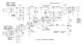
Hi, I'm stucking with this battery charger and have some questions.
1, The current on R2 ( in circuit is 1mA ) but my result isn't similar. My result is 1.7mA, i have used 39V, when the current flow through 2 diode, the voltage is 37.6V, add with Vbe = 0.62V, i got 38.22. Thus, IR2 = 1.7mA. If I used detail in circuit, Vbe would be 0.93. So which is correct and how to calculate Vbe, I have read in datasheet, it only shows me the maximum of Vbe?
2, The second problem is beta of transistor, you can see Q1, Q2 in circuit, with IB2 = 0.2mA, i have IE2 = 10mA -> beta = 50 and IB1 = 10mA, IE = 1A -> beta = 100. So how to determine beta?
3, I have tried to simulate on Proteus, but result is different (Image below). I replace source circuit by DC source and add R7 resistor in my simulation.
4, I'm not clearly understand of diode D4, Q4 and Q5 function. Anyone can explain those ones?
I have to use google translate to translate my questions , so please ignore English grammar error.
Thank you very much.
Attachments
-
 69.6 KB Views: 19
 -
 532.8 KB Views: 15
")


