 Facebook
 Google
 GitHub
 Linkedin
Hello guys,
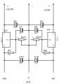
i need your help if possible. I created a dual voltage power supply using LM317 and a LM337 both in TO220. The problem is that when empty everything is ok but when I connect the load they heat up within two minutes also with heatsinks. I give a brief description of the circuit. The transformer generates me 17-0-17 Volt AC (150mA + 150mA I know it's small but it's just for testing) which rectified and stabilized become +22.8 0 -22.8 Volt DC. This is the input voltage to the voltage regulators. There are 6 of which three are negative and three positive where each one generates a different output voltage which is:
+/- 12 Volt
+/- 5 Volts
+/- 1.5 Volt
Let's leave out the 12 Volt that for the moment I don't have the possibility to test it, the measured currents are:
For the +1.5V and -1.5V 77mA.
For the + 5V I read 90mA and for the -5V 34mA.
The difference in current from + and - is due to the fact that the + V has to feed one more component.
I did some calculations so :
(22.8-5) * 0.090 = 1.6Watt for +5V
(22.8-5) * 0.034 = 0.6Watt for -5V
(22.8-1.5) * 0.077 = 1.6Watt both for + and - 1.5V
What i ask :
1) the correctness of the calculations and if exact, why the regulators heat with such low absorption?.
2) possible solutions.
As I said above these dual stages are 3 in parallel to 22.8Volt . If I wanted, I could intervene on every single entry of the regulators if the fact that they are in parallel does not generate further problems.
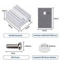
I attach the diagram of one of the three dual stages and the image of heatsink used.
Thanks.
i need your help if possible. I created a dual voltage power supply using LM317 and a LM337 both in TO220. The problem is that when empty everything is ok but when I connect the load they heat up within two minutes also with heatsinks. I give a brief description of the circuit. The transformer generates me 17-0-17 Volt AC (150mA + 150mA I know it's small but it's just for testing) which rectified and stabilized become +22.8 0 -22.8 Volt DC. This is the input voltage to the voltage regulators. There are 6 of which three are negative and three positive where each one generates a different output voltage which is:
+/- 12 Volt
+/- 5 Volts
+/- 1.5 Volt
Let's leave out the 12 Volt that for the moment I don't have the possibility to test it, the measured currents are:
For the +1.5V and -1.5V 77mA.
For the + 5V I read 90mA and for the -5V 34mA.
The difference in current from + and - is due to the fact that the + V has to feed one more component.
I did some calculations so :
(22.8-5) * 0.090 = 1.6Watt for +5V
(22.8-5) * 0.034 = 0.6Watt for -5V
(22.8-1.5) * 0.077 = 1.6Watt both for + and - 1.5V
What i ask :
1) the correctness of the calculations and if exact, why the regulators heat with such low absorption?.
2) possible solutions.
As I said above these dual stages are 3 in parallel to 22.8Volt . If I wanted, I could intervene on every single entry of the regulators if the fact that they are in parallel does not generate further problems.
I attach the diagram of one of the three dual stages and the image of heatsink used.
Thanks.
Attachments
-
 27 KB Views: 27
 -
 63.7 KB Views: 28


