headphone amplifier design

Thread Starter

damochi

Joined Feb 17, 2006
40
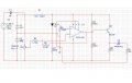
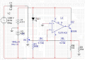
Need help with this circuit not sure if it's going to work i've simulated it on multisim and i'm not sure if i got the caculations for the resistors at the output stage right. R9 is the load driven 16ohms headphone delivering a power 0.5w . please help
 

Attachments

Audioguru

Joined Dec 20, 2007
11,248
The max output into 16 ohm headphones is about 263mW, not 500mW. It will be extremely loud and might blow your ears off.
Your circuit has problems:

1) You used a very low distortion opamp then added a transistor that has distortion, without including the transistor inside the negative feedback loop of the opamp so the opamp can reduce the distortion of the transistor.
2) You connected the volume control to the negative supply instead of to ground. Then the DC gain of the opamp forces its output to saturation at the positive supply.
3) You grounded the input offset adjustment pins 1 and 5. Then the opamp won't work properly.
4) You overloaded the output of the opamp with R2 and R3 that are not needed.
5) You have R7 but the opamp has FET inputs so it has no input bias current Io R7 is not needed.
6) The batteries will quickly drop below the minimum supply voltage of 7V for the TL071.
7) Each battery needs a supply bypass capacitor.
8) The output transistor operates as class-A into R8 with a current of almost 1A! A huge waste of battery power. A complimentary pair of transistors operating in class-AB will save a lot of power.
9) Your schematic sofware is full of measles dots.

If you include the transistor or a complimentary pair of transistors inside the negative feedback loop of the opamp then the output coupling capacitor is not needed.
 

Attachments

Top