Hardware advice, 5V to 24V by using a tension divider bridge

Thread Starter

Abdoul_91

Joined Dec 24, 2019
20
Hello to All,

I'm currently working on design and i was wondering if it was possible to have some help about it.
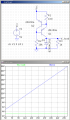
i wanna be able to have an input wich can work from 5V to 24V by using a tension divider bridge and 3V3 zener diode with 5mA because the chip input only accept 3V3
this is the idea i was going for :
1609325952119.png
Thank you for your help
 
Last edited by a moderator:

AlbertHall

Joined Jun 4, 2014
12,346
That is not going to work as the 100k resistor will only allow about 0.2mA to flow even with 24V input.
I don't think it is practical. The voltage across the 100k (why are all the resistors named R7?) would vary between 1.7V and 20.7V - that's a ratio of over 12.
The minimum current must be at least 5mA for the LED and that means that the current at 24V input will be nearly 61mA and the dissipation in that input resistor would be over 1.2W.

I would suggest a non-inverting CMOS gate (or two inverting gates), powered from the 3.3V supply and the input fed by a high value resistor (perhaps 100k) with a schottky diode to prevent the gate input going much above 3.3V.
 

Thread Starter

Abdoul_91

Joined Dec 24, 2019
20
That is not going to work as the 100k resistor will only allow about 0.2mA to flow even with 24V input.
I don't think it is practical. The voltage across the 100k (why are all the resistors named R7?) would vary between 1.7V and 20.7V - that's a ratio of over 12.
The minimum current must be at least 5mA for the LED and that means that the current at 24V input will be nearly 61mA and the dissipation in that input resistor would be over 1.2W.

I would suggest a non-inverting CMOS gate (or two inverting gates), powered from the 3.3V supply and the input fed by a high value resistor (perhaps 100k) with a schottky diode to prevent the gate input going much above 3.3V.
the resistor are named R? because i didn't annotate yet on altium that's why.
And the value of resitance that i choose was R1=10K and R2=20K for the 5V to 3V3 and i tough by using a zener i will be able to have 3V3.
About the solution you are talking about could you show me any scetch so i can undersatnd the idea please ?
thank you very much for your help
 

jpanhalt

Joined Jan 18, 2008
11,087
The zener breaks down at about 3.3V. It is somewhat like a short until the voltage drop across the upper left resistor = Vinput - 3.3V. That resistor is shown as 100k. Is it's actual resistance 10k, 20k or what? Assuming an input of 24V, the drop across it will be 24 -3.3 = 21.7V. 21.7V/10k = 2.17 mA. That is the total current through that resistor.

The voltage at GP will be 3.3V, but available current will be less as the other resistors and diode are in parallel to it.
 

Thread Starter

Abdoul_91

Joined Dec 24, 2019
20
The zener breaks down at about 3.3V. It is somewhat like a short until the voltage drop across the upper left resistor = Vinput - 3.3V. That resistor is shown as 100k. Is it's actual resistance 10k, 20k or what? Assuming an input of 24V, the drop across it will be 24 -3.3 = 21.7V. 21.7V/10k = 2.17 mA. That is the total current through that resistor.

The voltage at GP will be 3.3V, but available current will be less as the other resistors and diode are in parallel to it.
the actual resistor is 10K
so you think that the design could work ?
 

AlbertHall

Joined Jun 4, 2014
12,346
The zener breaks down at about 3.3V. It is somewhat like a short until the voltage drop across the upper left resistor = Vinput - 3.3V. That resistor is shown as 100k. Is it's actual resistance 10k, 20k or what? Assuming an input of 24V, the drop across it will be 24 -3.3 = 21.7V. 21.7V/10k = 2.17 mA. That is the total current through that resistor.

The voltage at GP will be 3.3V, but available current will be less as the other resistors and diode are in parallel to it.
Have you allowed for the current that will flow to the LED?
 

jpanhalt

Joined Jan 18, 2008
11,087
@AlbertHall
An LED is a diode, and yes, it needs to be included in any calculation as I stated. But we don't know for sure what the resistor values are since the labels in the original schematic were not accurate.
 

AnalogKid

Joined Aug 1, 2013
11,036
Please clarify: Is the 3.3 V output used to power a downstream circuit, or is it only an input signal?

I was heading toward a current source suggestion, but hrs beat me by 3 minutes.

ak
 

jpanhalt

Joined Jan 18, 2008
11,087
Hello,

@jpanhalt , I have blown up the image and can read the values:
View attachment 226267
R1 seems to be 100K, R2 seems to be 18K.

Bertus
I could read the values before that help. Fortunately, the TS has clarified some of the values:
Abdoul_91 said:
And the value of resitance that i choose was R1=10K and R2=20K for the 5V to 3V3 and i tough by using a zener i will be able to have 3V3.
Since the labels are all question marks, that still left ambiguity. In post #6, the TS clarified that the upper left resistor (R1 in my schematic) was 10k.

Based on that and a 24V supply (or any other supply voltage, but as an example, I chose 24V), one can calculate the maximum current that can be drawn and still remain in regulation by the zener. The rest is still guesswork, and I have other things to waste time on.
 

ronsimpson

Joined Oct 7, 2019
3,037
This version; sees anything above 4.5V as a 1 and below as a 0. 4.0V if R5=open, play with value to get 5.0V if you want.
A1 is a CMOS buffer or inverter.
The LED is after the buffer so input voltage will not effect the brightness.
Q1 can pull above 3.3V supply so R4 will limit the current into A1 input to protect it.
Much of the current in R2 pulls up on the 3.3V supply so you need to have more than 2mA of load some where on the 3.3V supply.
1609348487783.png
 

BobTPH

Joined Jun 5, 2013
8,942
I am still not convinced he is not trying to power the chip with the 3.3V output, what kind of input is likely to take 5mA? I assumed this when I read the original post.

Bob
 
Top