Half bridge inverter/mosfet question.

Thread Starter

Runs212

Joined Mar 12, 2015
57
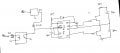
I'm using a half bridge driver to drive a mosfet fqa55n25. It's input is above 10v, vdd is at least 12v. I noticed the 100ohms resistor connecting the driver to the mosfet was heating up. I also noticed my input frequency was at 400hz. Could the low frequency explain why it was heating up?
 

Thread Starter

Runs212

Joined Mar 12, 2015
57
This is my last resort before i have to do a demonstration for the semester and I'd appreciate some help. Attached is a schematic of my project and teh waveforms i'm getting on the driver. I didn't connect it to the mosfet yet because the second signal was outputing ~5V. The first signal is correctly outputing the needed ~10V. I can't seem to figure out why one output on the driver is wrong. The current frequency is about 2Khz. I'm expected to use 110Khz but at that frequency, the signal gets seriously distorted. I'd appreciate any help that can be offered. This is for my senior design first semester project due in 2 days.
 

Attachments

kdillinger

Joined Jul 26, 2009
141
The COM was grounded. I mistakenly omitted that on the schematic. also the cap value to the right is 4.7uF.
If you zoomed in on the falling edge of the channel that is giving you problems (which channel BTW?) is there any funny business?
The time base from your first scope plot is 100us/div. If this is happening when nothing is connected to the outputs, then one possibility is a bad part. You have a 80us time constant on the falling edge and that should not happen. Looks like you have a blown output stage, IMO. Some high resistance interacting with the gate capacitance.
Is this on a breadboard or PCB?
 

Thread Starter

Runs212

Joined Mar 12, 2015
57
Thanks for your responses. I agree the mosfet driver is probably blown. Both HIN and LIN are receiving the same input (~5V) and should have a similar output (>10V). This is on a breadboard btw.
 

kdillinger

Joined Jul 26, 2009
141
Thanks for your responses. I agree the mosfet driver is probably blown. Both HIN and LIN are receiving the same input (~5V) and should have a similar output (>10V). This is on a breadboard btw.
One thing to be careful of is the actual breadboard. I have seen parts shorted out because the person pushed the pins with enough force to get underneath the strip metal and into the next column.
 

Thread Starter

Runs212

Joined Mar 12, 2015
57
Hello Everyone, progress has been made in the project. However, when I connect a load to my circuit or connect it to a receiver circuit, my MOSFET heats up quickly. I am thinking something shorting somewhere. I could be wrong. Could you look at my schematic and bounce off some ideas with me? Thanks.
 

Attachments

Top