I think that will give me a problem then, with +-5v driving my coil at its resonant frequency, I get a peak of around 60-70v. Do all mosfets have a built in diode and will that rule them out for my application?
Thanks Geoff
I've just been poking my breadboard with the oscilliscope, while I have 65v peak to peak across the coil, the driver pins of the chip still only have 5v above ground on them. Ie no more than their supply, does this mean I could use mosfets? If so would the chip I've metioned in my previous post be suitable or does anyone have a suggestion for a mosfet pair I could use.
Thanks Geoff
Since you did not post a schematic with a "resonant coil", a "U2270 driver IC" and you did not show which are its "driver pins" then we don't know how the output can be 65V p-p when its supply is only 5V.
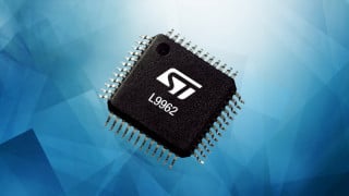
The Mosfet H-bridge chip has diodes from its outputs to the supplies so they will prevent the outputs from having a voltage more than 1V above the positive supply voltage and prevent the outputs from having a voltage more than 1V more negative than the negative supply voltage.
Sorry if I wasn't clear, the u2270b has drivers for a coil/capacitor circuit, I think I mentioned in my first post I was driving a LC circuit. At present with a +-5v driving the LC tank the voltage across the coil is +-32v (65v peak to peak), its resonant at around 130khz. The voltage across the drivers remans +-5v. I would like to drive it at a higher voltage to increase the current throught the coil and thus the read range of the circuit. As the u2270b drivers switch from +5v to ground I was hoping I maybe able to use its output to drive a H bridge and then my lc tank at a higher voltage. Do you think the mosfet H-bridge chip would be suitable or do I need to look at doing it another way?
Thanks Geoff
The U22790B is part of an RFID receiver. Its tuned LC circuit is SERIES resonant, not parallel resonant so the coil and/or capacitor can have a p-p voltage much higher than the supply voltage. The diodes are also in the outputs of the U2270B IC so the diodes in Mosfets should also not conduct.
Thank you for that, I've got a couple of the ZXHMC6AN078 H bridge chips. I've been playing about with one, its kind of unclear which way round the pinout should be read as theres no dimple on them as shown in the data sheet? I must have had it right I think as I tried it the other way round and a puff of smoke came out! Good job I got two.
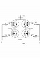
This is how I connected it up first, the resistors I used are 1500k and when I turned it on I had points A and B grounded. I expected to measure 5v across V1 and V2 when I moved point A to 5v, I didn't it remained at 0.3v the same with A to ground and B at 5v. Obviously I have got the wrong end of the stick somewhere and didn't want to cook the 2nd one. This is my first attempt at using mosfets so any help would be welcome.
Thanks Geoff
A 1500k resistor is 1.5M which is much too high. It should be 1.5k or less so that the Mosfets can turn on and turn off quickly.
When A and B have the same voltage then the voltages at P1 and P2 will be the same.
The bridge is turned on when one input is high and the other input is low but the output voltage becomes forward or reversed.

 Facebook
 Google
 GitHub
 Linkedin