H bridge [Schematic included ] loading problems

Thread Starter

thekaiser11234

Joined Apr 29, 2012
25
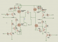
Hello i have been working on h bridge for awhile its my 1st design as you see below

using it to control 14amp rater 24 volt (250 watt) motor

controlling using Arduino (500hz frequency )

(1-0) move in 1 direction
(0-1) other direction
(1-1) Break

the upper side is P channel IRF9540 or 9540N i used both
http://www.irf.com/product-info/datasheets/data/irf9540n.pdf

the lower side is N channel IRF540 or IRF540N also :)
http://www.irf.com/product-info/datasheets/data/irf540n.pdf

for level shifting ( 5 to 12v)
im using BC547 NPN

http://www.futurlec.com/Datasheet/Transistor/BC547.pdf

to keep the voltage (VGS and VSG ) for P and N transistors
im using 12 v zener

here they name it only by voltage and wattages
im currently using 1 watt zeners

the max available is 5 watt

R zener is 1k in case its not obvious enough !

the driver works fine without loading
but if i add them my sort of cart project
15k load

the motors dont seem to move the transistor HEAT AND HEAT then they blow !

can you guide me whats the problem

sorry for the long post ,just hoping for help asap !

Thank you to infinity :D
 

Attachments

praondevou

Joined Jul 9, 2011
2,942
1. Are you using a fixed deadtime or none at all (relying only on the gate drive circuitry delays) ?
2. Are the MOSFETs mounted on heatsinks?
3. "load 15k". does that mean 15kOhm?

4. battery voltage is 24V?


PS: please use points at the intersections where a electric connection between lines is.
 

Thread Starter

thekaiser11234

Joined Apr 29, 2012
25
1. Are you using a fixed deadtime or none at all (relying only on the gate drive circuitry delays) ?
i dont seem to understand totally what you mean
please clarify


2 Mosfets are mounted on heat sinks yes

3. sorry i mean loading the motors with 15kg load sorry for confusion

4. battery voltage is 24V yes !

thanks for the hint i will do this later
is any thing else not obvious in the circuit ?
 

praondevou

Joined Jul 9, 2011
2,942
1. Are you using a fixed deadtime or none at all (relying only on the gate drive circuitry delays) ?
i dont seem to understand totally what you mean
please clarify


2 Mosfets are mounted on heat sinks yes

3. sorry i mean loading the motors with 15kg load sorry for confusion

4. battery voltage is 24V yes !

thanks for the hint i will do this later
is any thing else not obvious in the circuit ?
1. What is the sequence of IN1, IN2? Is there a time when both are off?

3. What does that mean in terms of motor current?
 

Thread Starter

thekaiser11234

Joined Apr 29, 2012
25
1- through the code they shall be both on or (one and the other off ) in case of no movement break is activated

3-well im using 2 motors of the motors included above
they both consume averagely 20 amp or lil more which is 10 ampere for each motor

(also i wana ask is it a problem if i let both off the same time ? )
 

Thread Starter

thekaiser11234

Joined Apr 29, 2012
25
Change 10k base resistor to 1k. Your not saturating the transistor. You should also put diodes across drain and source of your mosfet.
Thank you for replying

about the 1k resistor wont this consume more current from my controller ??


and for the fly back diodes in the datasheets there are body diodes in each fet
and they can take 20 ampere which isnot available in market here
 

praondevou

Joined Jul 9, 2011
2,942
1- through the code they shall be both on or (one and the other off ) in case of no movement break is activated

3-well im using 2 motors of the motors included above
they both consume averagely 20 amp or lil more which is 10 ampere for each motor

(also i wana ask is it a problem if i let both off the same time ? )
20A for a IRF540 is to much IMO. Even if the datasheet says 22A@25°C (or 15A@100°C). You should put more than 1 in parallel. Also you didn't say the size of the heatsink. Did you use thermal compound?

You are applying 24V battery voltage to the gates of Q4 and Q8 when you want them to turn on.
The gates of Q6 and Q8 get -22V at their gates (referenced to the source terminal) when turned on. That's too much.

Example:
IN2 = 5V
IN1 = 5V
Q8 conducts
Q7 does not conduct

IN2 = 5V
IN1 = 0V
Q8 does not conduct
Q7 conducts

Question: Is there a time when both transistors of one leg conduct? This is a short circuit for the battery, however it can be a very short time and maybe the wire inductances from the battery are long enough to limit the current for this short amount of time. The correct thing would be to drive the MOSFETs with gate signals that assure a certain time where both MOSFETs of one leg are OFF (deadtime). I would choose a few us for this application.

In short:

- Check if there is cross-conduction.
- Adjust your gate resistor dividers in order to apply about 15V / -15V to them.
- Use at least 2 of those MOSFETs in parallel for 20A or use other MOSFETs
 

Thread Starter

thekaiser11234

Joined Apr 29, 2012
25
20A for a IRF540 is to much IMO. Even if the datasheet says 22A@25°C (or 15A@100°C). You should put more than 1 in parallel. Also you didn't say the size of the heatsink. Did you use thermal compound?

thats really what is happening sorry for confusion i made 2 motor drives 1 for each motor so yes they are working in parallel
about heatsink im using 4 heatsinks 1 for each FET with largest size available
and if you are talking about that white thingy you put behind the Fet yes im using one


You are applying 24V battery voltage to the gates of Q4 and Q8 when you want them to turn on.
The gates of Q6 and Q8 get -22V at their gates (referenced to the source terminal) when turned on. That's too much
.
you mean Q4 and Q8 ?
isnot the zener diodes doing the job to limit the voltage to 12 of gates ( referenced to source ) ?
am i missing something obvious ?


about the voltage devision the 10k and 1k resistors and changing them for (15 and -15 ) thingy isnot the zener diode doing the job ?

or im still missing something ?
 

Thread Starter

thekaiser11234

Joined Apr 29, 2012
25
Sorry about that, yes you are right. It's partly due to the schematics unusual layout.
srry for that i promise this wont happen next time :)

so what do you think the problem is ?
the frequency ?
or the FETS aint good enough ??

or resistor values ??

or i need higher wattages zener ??


this is confusing for me as a beginner

Thanks in advance
 

mhastie1234

Joined Feb 10, 2012
29
You have to put a smaller resistor on the base of the transistor. With a 10k resistor you are not saturating you transistor. With no load it might work fine. Adding a load WILL fry it every time.
 

Thread Starter

thekaiser11234

Joined Apr 29, 2012
25
You have to put a smaller resistor on the base of the transistor. With a 10k resistor you are not saturating you transistor. With no load it might work fine. Adding a load WILL fry it every time.
also how would loading fry them ??

loading is on fets BC547 is only for lvl shifting
 

Thread Starter

thekaiser11234

Joined Apr 29, 2012
25
ok guys im still trying with this circuit

i tried to decrease the load and see whats gonna happen

the robot moved

but too slow the first voltage was about 3 v or something and increases as the motor moving within a noticable speed

the current drawn is around 5 ampere

any thoughts ? :S
 

mhastie1234

Joined Feb 10, 2012
29
If you dropped your 10k to 1k on the base. Try removing the 1k resistor on the gate of the mosfet and see if that helps. On the data sheet its 5.1ohm
 

Mhlengi

Joined Sep 28, 2012
4
Hi, I am building an H Bridge to drive a 2A @ 12V motor and I am using a 555 timer for the signal, so I tested the circuit at 7.5V DC but the motor only rotates in one direction, I use a 4.7k variable resistor for controlling the motor and this only makes the motor speed slow when the variable is turned fully anti-clockwise n the speed fast wen the variable is turned fully clockwise. Any suggestions on how I can change the direction.
 

Audioguru

Joined Dec 20, 2007
11,248
Hi, I am building an H Bridge to drive a 2A @ 12V motor and I am using a 555 timer for the signal, so I tested the circuit at 7.5V DC but the motor only rotates in one direction, I use a 4.7k variable resistor for controlling the motor and this only makes the motor speed slow when the variable is turned fully anti-clockwise n the speed fast wen the variable is turned fully clockwise. Any suggestions on how I can change the direction.
Please start your own thread and attach the schematic.
 
Top