 Facebook
 Google
 GitHub
 Linkedin
Good evening everyone, I am on an electrical engineering team here at Texas A&M and we are doing a project on a wheelchair for a quadriplegic man. We are currently debugging the motor controllers and have been slugging through the whole process. This project is a three year project and we received the motor controllers with a prevalent issue in regards to a current problem associated with a higher load such as when the user attempted to go up hills or a slight grade. Further debugging seemed to show that the motor controllers were functioning correctly and we started aiming at the processor, which is an ATmega2560. So in order to cross that off of the list. So I looked around the web and slightly copied the structure of someone elses code used on an Arduino Mega since its the same chip. The code is shown below.
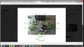
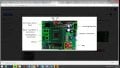
So we have the directional bits that are either high or low in order to differentiate between forward and reverse and a PWM line going to the Motor Controllers. These digital output from the mega board are at 4.8V. The image of the Motor Controllers is attached. I have found that when connecting the PWM onto the header in attempts to have the signal go through the transistors gave no response from the motors. However if I placed the PWM signal directly to the input pin of the H-Bridge I can get a varying voltage on the motor terminals from 0-24V. It does fluxuate about 2v, which I feel may be alot, but this issue may be a real problem. Also the Left Motor Controller does not respond the same way the right one does. The right H-Bridge does not respond at all (so its only able to function in reverse) and the left H-Bridge, when attached to the pwm of the arduino it was stuck at 24v no matter the duty cycle of the PWM signal, so there is definitely something wrong there. If anyone has any insight to the reasoning behind this please feel free to ask questions and thank you for ya'll input.
//Keyboard Controls:
//
// 1 -Motor 1 Left
// 2 -Motor 1 Stop
// 3 -Motor 1 Right
//
// 4 -Motor 2 Left
// 5 -Motor 2 Stop
// 6 -Motor 2 Right
// Motor 1
int dir1PinA = 32;
int dir2PinA = 34;
int speedPinA = 10; // Needs to be a PWM pin to be able to control motor speed
// Motor 2
int dir1PinB = 36;
int dir2PinB = 38;
int speedPinB = 11; // Needs to be a PWM pin to be able to control motor speed
void setup() { // Setup runs once per reset
// initialize serial communication @ 9600 baud:
Serial.begin(9600);
//Define L298N Dual H-Bridge Motor Controller Pins
pinMode(dir1PinA,OUTPUT);
pinMode(dir2PinA,OUTPUT);
pinMode(speedPinA,OUTPUT);
pinMode(dir1PinB,OUTPUT);
pinMode(dir2PinB,OUTPUT);
pinMode(speedPinB,OUTPUT);
}
void loop() {
// Initialize the Serial interface:
if (Serial.available() > 0) {
int inByte = Serial.read();
int speed; // Local variable
switch (inByte) {
//______________Motor 1______________
case '1': // Motor 1 Forward
analogWrite(speedPinA, 255);//Sets speed variable via PWM
digitalWrite(dir1PinA, LOW);
digitalWrite(dir2PinA, HIGH);
Serial.println("Motor 1 Forward 255"); // Prints out “Motor 1 Forward” on the serial monitor
Serial.println(" "); // Creates a blank line printed on the serial monitor
break;
case '2': // Motor 1 Stop (Freespin)
analogWrite(speedPinA, 0);
digitalWrite(dir1PinA, LOW);
digitalWrite(dir2PinA, HIGH);
Serial.println("2. Motor 1 Stop");
Serial.println(" ");
break;
case '3': // Motor 1 Reverse
analogWrite(speedPinA, 245);
digitalWrite(dir1PinA, LOW);
digitalWrite(dir2PinA, HIGH);
Serial.println("3. Motor 1 forward 245");
Serial.println(" ");
break;
//______________Motor 2______________
case '4': // Motor 2 Forward
analogWrite(speedPinA, 235);
digitalWrite(dir1PinA, LOW);
digitalWrite(dir2PinA, HIGH);
Serial.println("4. Motor 1 Forward 235");
Serial.println(" ");
break;
case '5': // Motor 1 Stop (Freespin)
analogWrite(speedPinA, 220);
digitalWrite(dir1PinA, LOW);
digitalWrite(dir2PinA, HIGH);
Serial.println("5. Motor 1 forward 220");
Serial.println(" ");
break;
case '6': // Motor 2 Reverse
analogWrite(speedPinA, 200);
digitalWrite(dir1PinA, HIGH);
digitalWrite(dir2PinA, LOW);
Serial.println("6. Motor 1 rEVERSE 200");
Serial.println(" ");
break;
case '7': // Motor 2 Reverse
analogWrite(speedPinA, 235);
digitalWrite(dir1PinA, HIGH);
digitalWrite(dir2PinA, LOW);
Serial.println("7. Motor 1 Reverse 235");
Serial.println(" ");
break;
case '8': // Motor 2 Reverse
analogWrite(speedPinA, 5);
digitalWrite(dir1PinA, HIGH);
digitalWrite(dir2PinA, LOW);
Serial.println("8. Motor 1 reverse 5");
Serial.println(" ");
break;
default:
// turn all the connections off if an unmapped key is pressed:
for (int thisPin = 2; thisPin < 11; thisPin++) {
digitalWrite(thisPin, LOW);
}
}
}
}
Attachments
-
 250.7 KB Views: 9
 -
 265.6 KB Views: 7


